Continue to Site

Welcome to our site!

Electro Tech is an online community (with over 170,000 members) who enjoy talking about and building electronic circuits, projects and gadgets. To participate you need to register. Registration is free. Click here to register now.

  • Welcome to our site! Electro Tech is an online community (with over 170,000 members) who enjoy talking about and building electronic circuits, projects and gadgets. To participate you need to register. Registration is free. Click here to register now.

Tachometer Driver Board for 90's Mopar's

Sailorman2005

New Member
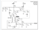
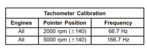
I have a 94 Dodge Dakota where the tachometer was failing. Upon startup the needle would float and then go full clockwise deflection, settling on the overdriven section of the meter. I pulled the old drive module from the back of the instrument cluster and began troubleshooting for bad parts and traces. I found Q2 and Q3 open on the collector side. C5 was reading 60uF vice 68 out of circuit. Not too bad for 20% tolerance. My issue is I have no datasheet on the 14 pin DIP and could not find this part anywhere online. The drive board part number is 4375410. It is a common board used in many Chrysler vehicles of the 90's. However, finding a good working one is sketchy at best. I would like some input on how I can test this board for a good input/output utilizing the ecm signal for tach. However, i do not know if this is just a 5v signal with an alternating squarewave or something else. If anyone have experience or knowledge on how to best test this circuit board I would be forever grateful. I will attach a diagram of the only schematic I could find. According to the repair manual the ecm sends a signal with the following for calibration reference.
 

Attachments

  • tach schematic.PNG
    tach schematic.PNG
    228.6 KB · Views: 39
  • Tach calibration.PNG
    Tach calibration.PNG
    28 KB · Views: 34
I did some more testing and found that the biased voltage to pin 13 from Q1 to the chip was non existent. I used a function gen to test for signal to pin 10 and that line works. I suspect my 12v line in is not powering the chip and have no signal out. When I receive some replacement parts I will perform another test.
 
Last edited:
So, an update on the circuit. I replaced Q2 and Q3 on the board and now have a good voltage at pin 13 of the 14 pin DIP. (this chip is still non-existent). I am still testing for a good tach signal out to pin 7 and will update when I have a conclusion on the functionality of this board.
 

Latest threads

Back
Top