Continue to Site

Welcome to our site!

Electro Tech is an online community (with over 170,000 members) who enjoy talking about and building electronic circuits, projects and gadgets. To participate you need to register. Registration is free. Click here to register now.

  • Welcome to our site! Electro Tech is an online community (with over 170,000 members) who enjoy talking about and building electronic circuits, projects and gadgets. To participate you need to register. Registration is free. Click here to register now.

Tank sensor help !

Status
Not open for further replies.

yusuf

Member
Hello friends :

I was using three separate sensor circuit to sense water , empty & full tank condition...

It also takes place and it's too bulky..

So I used the unused gates from old sensor circuit..
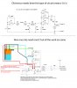
You can see my old sensor circuit in my attachment...

I have used the unused gates of my old sensor circuit to sense water & full tank condition..

I have made this new circuit which you can see in my attachment...

But the problem is ....

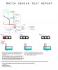
I have attached the problem report with the test I have done in my attachment...

====

If I touch common sensor wire + empty sensor wire = the empty led glows..
Or If I touch common sensor wire + water sensor wire = the water led glows
or If I touch common sensor wire + full sensor wire = full led glows..

But by :
touching common sensor wire + empty sensor wire + full sensor wire = all led turns off..
or by touching common sensor wire + empty sensor wire + water sensor wire = all led turn off

If I add the 3rd sensor wire all led switched off...
It work when I use on two sensors wire..

But I want :

By touching common sensor wire + empty sensor wire + full sensor wire = empty & full sensor led glow.
or by touching common sensor wire + empty sensor wire + water sensor wire = empty & water sensor led glow..


Please have a look on my both attachment and kindly help !!

Thanks in advance..

:)
 

Attachments

  • REVSED_NEW.jpg
    REVSED_NEW.jpg
    208.3 KB · Views: 157
  • Repsort.jpg
    Repsort.jpg
    184.1 KB · Views: 127
it seems your oscillator dies when you load all three inputs. if possible check the output in an oscilloscope. other wise modify your oscillator to use two gates for some stable out put and check with two NAND gae outputs in parellal or use a transistor to amplify the wave.
 
The gates of the CD4093 can not drive LEDs by them selfs. Thats why the orginal had 3 to drive the 1 LED. You need somthing to drive the LEDs in your new circuit maybe a transister for each LED.
 
Thanks friend for reply !
Can someone can provide a proper circuit if possible..
I will be very! :)
Thanks in advance..
 
How this circuit is working !

Hello Friends ,
Can any body give me the detail of how this sensor circuit is working....

Please give me the complete detail...

I know it is capacitive sensing...

But the component which are in between ... how they are working...

I have attached the sensor circuit in my attachment 1

It is water sensor circuit...

I have traced this circuit... but dint get any clue or idea how it is working....
 
Can any body give me the detail of how this sensor circuit is working....
Please give me the complete detail...
Can't you see that the sensed signal is AC and is rectified by diodes into DC pulses then filtered by a capacitor into smooth DC?
Do you know what the paralleled CD4093 Schmitt trigger gates do when fed the varying DC voltage?
 
I know it is capacitive sensing...
No; it senses a change in resistance between the probes (which are AC-coupled to the rest of the circuit). When water is present between the probes the resistance is low enough for the rectified AC signal from oscillator U1 to rise above the Schmitt threshold of the gates U2, U3, U4. The gate outputs go low and turn on the LED. Between them, gates U2-U4 can just about sink enough current for the LED.
One CMOS gate acting as an oscillator does not have enough output current to drive three probes.
 
I didn't understood friends properly ... can any one give me the good detail and step by step instruction for better understanding...

As I am new in this field , so I want to know how it is working 1
Thanks..
 
I didn't understood friends properly ... can any one give me the good detail and step by step instruction for better understanding...

As I am new in this field , so I want to know how it is working 1
Thanks..
I think there is a language problem (we speak English, Yusuf has a different language) and Yusuf does not understand the basic of electronics.
Does anybody have a couple of years or more to teach him English and the basics of electronics?
 
I think there is a language problem (we speak English, Yusuf has a different language) and Yusuf does not understand the basic of electronics.
Does anybody have a couple of years or more to teach him English and the basics of electronics?

I understand English properly... But I am not understanding the circuit which is explained in very technical manner...
I want the explanation easy ..... and step by step method...
Because i am new in electronics... so It takes little time to understand any circuit...
 
What part of alec_t's explinashoin in post #7 did you not understand?
 
The circuit is very simple. It was explained (very well) with technical details because it is a technical circuit.
 
Status
Not open for further replies.

New Articles From Microcontroller Tips

Back
Top