Continue to Site

Welcome to our site!

Electro Tech is an online community (with over 170,000 members) who enjoy talking about and building electronic circuits, projects and gadgets. To participate you need to register. Registration is free. Click here to register now.

  • Welcome to our site! Electro Tech is an online community (with over 170,000 members) who enjoy talking about and building electronic circuits, projects and gadgets. To participate you need to register. Registration is free. Click here to register now.

Tektronix CH1 & CH2 beams erratic suddenly

Status
Not open for further replies.

fadik

New Member
Hi electro-tech members,

I just acquired my first Oscilloscope, a Tektronix 465B off of ebay, took a chance and got
it untested sold as is for $100 (shipped to my door step).

I powered it up, and did some initial testing, made sure both channels behaved OK when grounded (postioned on GND) and then tested against the calibration u-shaped link and saw
a nice square wave on both channels for the device's age and unknown untested it was all OK.

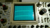
A couple of days later I powered it up and saw that CH1 was behaving erratic, it was Grounded and was showing a strange wave, i tested CH2, it exhibited the same symptoms.

I played around with different settings, different cases and all didn't make sense. Even the calibration wave form wasn't showing and my father helped as well as he has more extensive knowledge with oscilloscopes in general.

I have a GIF file that shows both channels grounded and shows a short animation of what i am seeing.

Hopefully someone here might help me get this working again, perhaps this can be an easy fix.

thanks for your help

Fadi
 

Attachments

  • WP_20130415_15_53_47_Cinemagraph.gif
    WP_20130415_15_53_47_Cinemagraph.gif
    859.8 KB · Views: 417
As both channels are affected the same way at the same time, my guess would be a power supply problem.
Maybe even an EHT problem. Can you hear it "ticking" as the EHT is sparking somewhere?

JimB
 
Thanks JimB for the reply.

I am not sure what an EHT is, I do have the service manual in PDF format and it is non searchable so its a bit of a pain to look
up information in it. With that said, I do not hear any ticking sound from the device.

Do you have any suggestion on how to proceed with testing? how bad does it sound to you at the moment?

Thanks

UPDATE:
Without getting into too much details of what happened, this is how the scope is now :( :
WP_20130415_006.jpg

UPDATE 2:
After some thought, the LEDs for the active channels, grid illumination lights, Trigger light...etc are all dead!
this is looking more like an issue with a power supply perhaps? any pointers on how to proceed are appreciated.
 
Last edited:
EHT = Extremely High Tension

The EHT is the supply, around 10 to 15 thousand volts which is used to accelerate the electrons to hit the screen and make a bright display.

Considering the latest state of your fault, I would say that it is not the EHT but definitely a power supply.
Where to go from there I do not know, I have no experience of repairing a Tek 465. (I have used one a few times, but that is all).

JimB
 
Thanks JimB.

I am troubleshooting the power supply circuit based on the service manual's schematics.
the Test Points:
110v measures 101v
+5 measures 2.6v
+55 measures 47v
+15 measures 0v
-8 measures 0.6v

I looked at component # U4411 which is an OP AMP, the input voltage to PIN-8 is 3.6 - 4v where it should be 26v or so.

I bought a new OP AMP IC, TL082 (same pin out and hopefully close enough spec) it didn't work, the voltage on pin-8 is still ~4v

Thanks for your help in all cases, i'll try to continue hitting this, in the meantime perhaps someone might have experience with this
specific model and/or problem.

Thanks

EDIT:
I over looked some pages, there are specific ones on how to troubleshoot power supply issues, I'll follow those step by step and see
what comes out of it.
 
Last edited:
JimBs comments in red
the Test Points:
110v measures 101v
+5 measures 2.6v
+55 measures 47v
+15 measures 0v
-8 measures 0.6v

I looked at component # U4411 which is an OP AMP, the input voltage to PIN-8 is 3.6 - 4v where it should be 26v or so.
I bought a new OP AMP IC, TL082 (same pin out and hopefully close enough spec) it didn't work, the voltage on pin-8 is still ~4v
Because the +55v is more or less OK, I suspect that U4411 is OK.
I suggest that you put back the original.


The voltage at pin 8 of U4411 is significant.
On the schematic which I have just downloaded, it shows the voltage to be 22V.
The 22v is derived from the +55v line by a zener diode VR4608.


I suggest that you measure the resistor R4412, should be 4.7k.
You will probably have to disconnect one end of R4412 to get the correct resistance reading.


If R4412 is OK I suggest that the zener VR4408 is faulty.
 
Hi JimB
Thanks again.

I just read your reply when I came here to update. As it turned out, following the +15V (which was showing 0) isolation procedure revealed that
the horizontal position knob was grounded by mistake when I was re-inserting the knobs) as soon as I made sure it is placed and tightened
without the internal connections hitting the chassis everything returned back to the starting case of this post.
 
OK

Good that you fixed it.

JimB
 
Indeed.
So now back to isolating why the channels are being erratic and showing what is most likely noise.
 
Hi JimB
you were spot on with the power supply.
Capacitor C4419 (-8 UNREG) was replaced and all is good now.
Well relatively, both channels work ok, Channel 1 exhibits a thicker trace line and some fluctuation, but this is totally different and unrelated
to this, so i'll open up a new thread for that issue.

Thanks for the support.
 
Status
Not open for further replies.

New Articles From Microcontroller Tips

Back
Top