Continue to Site

Welcome to our site!

Electro Tech is an online community (with over 170,000 members) who enjoy talking about and building electronic circuits, projects and gadgets. To participate you need to register. Registration is free. Click here to register now.

  • Welcome to our site! Electro Tech is an online community (with over 170,000 members) who enjoy talking about and building electronic circuits, projects and gadgets. To participate you need to register. Registration is free. Click here to register now.

Tell your comment !

Status
Not open for further replies.

watzmann

New Member
Hi All ,

here is a circuit i have built before and it works very well , but due to a better PCB requirment in my robot project i'll build another one .

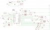
before getting into this step i'll upload the schemtic for the current one to hear your comments on it , i know it's not the good design it was my first one.

i need in my new board more safety design to avoid e.m.f.
could you please tell me how to do that.

as for the four optocouplers i have in the current design , 2 of them were burn , in my next PCB design i'll use 2n2222 after those optocouplers....is it right ?

i think the reason is they cannot afford more than 800mA , and i was connecting them to H-Bridge . it was so heavy .

anyway please tell me my mistakes to try to get a better design ,

thank you
 
as usual i forgot to upload the file :)
 

Attachments

  • main.jpg
    main.jpg
    393.3 KB · Views: 219
It is hard to follow the schematic, it is too small, so that some of the lines are non visible!
 
Krumlink said:
It is hard to follow the schematic, it is too small, so that some of the lines are non visible!
Your mouse cursor should be a little magnifying glass with a + in it. Click on the schematic, and voila! It gets bigger!
 
Hi Watzmann,

just to make sure: Are the outputs of your PIC active high or low? Normally they are active low. In that case your optocouplers are connected inversely.

Additionally I suggest to drive the OCs with an extra low power transistor. That way about 40mA for a safe drive current can be delivered. I doubt that the PIC can stand that load, and it will fry sooner or later (most probably sooner).

A hint to make good schematics: Never route a net wire through an IC. First it looks ugly and second nobody knows where the net is actually connected unless he has the original schematic and can trace the nets using Eagle.
 
It is also good practice to use flyback diodes on an H switch, as well as a local bulk capacitor.
 
Boncuk said:
Hi Watzmann,


Additionally I suggest to drive the OCs with an extra low power transistor. That way about 40mA for a safe drive current can be delivered. I doubt that the PIC can stand that load, and it will fry sooner or later (most probably sooner).

for example i can use 2n2222 , but do you mean to connect it after the optocoupler .

so it will be like that :

PIC signal then Optocoupler then 2n2222 , is it correct ?
 
Status
Not open for further replies.

Latest threads

New Articles From Microcontroller Tips

Back
Top