Continue to Site

Welcome to our site!

Electro Tech is an online community (with over 170,000 members) who enjoy talking about and building electronic circuits, projects and gadgets. To participate you need to register. Registration is free. Click here to register now.

  • Welcome to our site! Electro Tech is an online community (with over 170,000 members) who enjoy talking about and building electronic circuits, projects and gadgets. To participate you need to register. Registration is free. Click here to register now.

Three Pin Cap

Status
Not open for further replies.

linguist

New Member
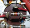
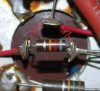
I have an old capacitor in a circuit that is 20uF 400v & has three pins.

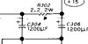
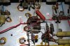
The outer casing is Aluminium & is used to fix the cap in place, I have attached a picture there is a DC voltage input & output but I am unsure what the third pin is for, is it just another DC output maybe it has various resistors connected to it?
There are no markings on the capacitor.

Can I change this capacitor to a normal two pin cap, if so how do I connect it, or do I need another three pin cap the same.

Cheers
 

Attachments

  • Three Pin Cap.jpg
    Three Pin Cap.jpg
    82.4 KB · Views: 147
Last edited:
It looks like a Dual-Section electrolytic .
(2 positive and 1 common negative)
Just 2 capacitors in one unit.
If you are replacing in a circuit I would use the same type.
You could disconnect one side (if only one is bad) and hang on another outboard capacitor of the proper value and voltage.
Once one section goes bad, it is best to replace the entire cap if the correct one is available though.
 
Last edited:
Thanks for the reply PatM,

So Is it basically like this attachment.

Cheers
 

Attachments

  • Dual Cap.jpg
    Dual Cap.jpg
    80.2 KB · Views: 189
You have the caps backward.
Capacitors common Neg are at top contact and attach to ground
Caps Positive contacts have resistor between
 
Last edited:
Could the extra terminal simply be a mechanical support to the casing which is grounded? The resistor would then just be a bleeder.
 
Last edited:
Pat M,

That is why it is a little confusing, on this circuit they have (looking at the picture) Voltage coming into the Centre pin & from there the Right pin supplies voltage to another part of the circuit.

The Left pin also has voltage that feeds another part of the circuit, so it's voltage in on the middle pin & then it branches out & feeds voltage from the right & left pin to other parts of the circuit.

Cheers
 
It's not going to be possible to positivly identify the component withotu the rest of the circuit as an example, take a bigger picture =)
 
Sceadwian,

Yes I should have supplied a better picture.

I have attached a couple of pictures with the working loaded voltages at each pin, this seems to work as some sort of voltage regulator?

Centre pin +420v in

Right pin +322v out

Left pin +194v out

These output voltages are what is required by the components it goes to.

There is a picture of the cap itself as well.

Cheers
 

Attachments

  • Cap.jpg
    Cap.jpg
    86.1 KB · Views: 145
  • Cap-2.jpg
    Cap-2.jpg
    177.3 KB · Views: 140
With the circuit powered off completely is there DC continuity (using any cheap meter) between the case and any of the leads? By continuity I mean less than 1ohm measured resistance.
 
Sceadwian,

No, there is continuity but high resistance.

Neal,

Could you posiible draw what you mean by three section cap so as I understand better, I know what your saying about three sections but they must all be linked together inside the cap somehow.

Like I mentioned the power goes in the centre lug & comes out the left & right lug.

Can I replace this with three seperate caps?

Cheers
 
Last edited:
I believe you have what Neal said. You have three 20 uF caps in a single can. Note the little symbols in the image of the can, a square, triangle and another symbol, each beside a value (20 uF). You should see those same symbols beside each bottom terminal. Each cap is a terminal to ground.

Ron
 
Last edited:
There is no connection between the 3 caps inside the can. The top terminal has 420v and is connected to the right terminal with a 15k giving you 322v. A 82k connects from the right terminal to the one on the left giving you 194v.
The only common connection between the 3 caps is the common negative side.
What makes you think the caps are bad? Yes you can replace with 3 individuals, but would be better to just get a new one in the can. It is a very common part to obtain and is/was used in many old tube power supplies for the B+ filtering.
 
The first attached image is your capacitor. Note that you see CODE MFD and VDCW. The code is the symbol you should see at the terminals on the bottom of the capacitor beside the connections. MFD is the value of the capacitor(s) expressed in micro-Farads and the VDCW is the Volts Direct Current Working value expressed in Volts DC.

The second image is what the capacitor(s) would actually look like from a schematic point. Three capacitors in a single can sharing the same common or ground point. Just as Neil describes it. Maybe the drawing will help?

Capacitors like this, as mentioned by Neil were common in early tube type radios as well as other electronic equipment like televisions and whatever, primarily as filter capacitors for the high voltages used with tubes.

When used in devices like radios if they failed open, you would hear a very loud and pronounced AC Hum from the speaker.

Ron
 

Attachments

  • Can Cap.jpg
    Can Cap.jpg
    86.1 KB · Views: 127
  • 3 Caps 1 Can.gif
    3 Caps 1 Can.gif
    4.5 KB · Views: 124
I'm blind, I didn't even see the solder tabs coming from the can on the bottom view, so it looks more like a four terminal device like Reload depicted.
 
Thanks to everyone with their replies, I can see now how it's works.

I wanted to replace it as I am starting to get a hum from my amplifier that wasn't their before, Thought it may have been this cap that was causing it.

Cheers
 
it may not be the cap causing the hum.
if it is the cap causing the hum,
its probably the first one straight on the ripple.
you can usually fit another single cap under the chassis,
and disconnect the original.

Or better still, a new one as mentioned,
but its liable to be expensive.

John :)
 
Thanks to everyone with their replies, I can see now how it's works.

I wanted to replace it as I am starting to get a hum from my amplifier that wasn't their before, Thought it may have been this cap that was causing it.

Cheers

You could try jumpering each cap(one at a time)and see if the hum goes away. Just use a cap with a rating of 450 or better and a MFD of 20 or higher is ok for testing purposes.
Other things can cause hum but this is a good place to start.
Make sure to observe polarity
 
Status
Not open for further replies.

Latest threads

New Articles From Microcontroller Tips

Back
Top