letsrelaythat
Member
Hi All,
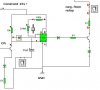
I have built the following circuit twice, and can't get it to work properly. I built it once on a smaller PCB, everything was very close together and didn't work, so I bought all the components again and built it on a much larger PCB, and spaced everything better.
The idea, is that I pass constant 12v+ to the top left wire, and when I pass 12v+ to the wire coming from the left in the middle, it should let the wire from the top right goto ground. This will most likely be a relay, used to keep a car running for a preset time, i.e a turbo timer.
The switch after the capacitor determines if the circuit is instantly broken or has a timed delay.
What happens is that the LED (which im using instead of the relay) comes on as soon as I give it 12v+, not when it has 12v+ and also the ON wire has stopped giving signal.
What should I look for on my PCB, any ideas where I may have messed up?
Thanks all in advance, :?
Tim.
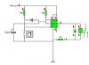