Continue to Site

Welcome to our site!

Electro Tech is an online community (with over 170,000 members) who enjoy talking about and building electronic circuits, projects and gadgets. To participate you need to register. Registration is free. Click here to register now.

  • Welcome to our site! Electro Tech is an online community (with over 170,000 members) who enjoy talking about and building electronic circuits, projects and gadgets. To participate you need to register. Registration is free. Click here to register now.

Toyota Fuel pump "ECU" replication...

Status
Not open for further replies.

dirtydoogle

New Member
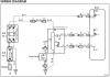
I am trying to replicate a Toyota fuel pump ecu from a 1990's soarer.
It's function is to run the fuel pump on 12V whilst the motor is cranking and under load/high RPM's. When at smaller throttle positions/idle it runs a 9V output to the pump.
I have done some auto electrics before, but, generally simplistic stuff. If anybody could help me by showing me a way of doing this, it would be brilliant.

I have thought about using a tachometric relay or circuit opening relay, but, cannot fathom how to make on change a voltage output....
I've been reading about comparators, but, I don't understand their function well enough. I have attatched a scematic diagram of the so called ECU.

Thanks from Doug in New Zealand!
 

Attachments

  • FPC.png
    FPC.png
    79.8 KB · Views: 1,059
How about running the pump in series with an adjustable power resistor (set once) to get the slower speed, and then shorting out the resistor with a FET or relay when full pump output is required? You could use a fancy PWM, but why bother?

The control logic will have to decide when the pump should run at full speed.
A. Cranking is easy. Just use the start contact on the ignition switch as an input.
B. RPM dependent? Use a re-triggerable multivibrator (555) to detect a preset RPM. Triggering signal coming from spark or existing tach pickup.
C. Full throttle? IC comparator (LM339) connected to TPS.
D. Other?
 
Last edited:
Doug,
you may wish to research 'ballast resistors' used in automotive ignition systems in times gone by....

The coil pos terminal was supplied with battery voltage, via a 'ballast' resistor, which dropped the supply to circa 9V.

When cranking, the 12v ignition switch supply sent to the starter solenoid was also applied to the coil side of the ballast resistor, bypassing it only when cranking.

You could possibly use a similar approach and also rig up a microswitch for WOT (Wide Open Throttle) which energises a relay to bypass the ballast resistor and supply battery voltage..

Regards.
 
+12V at 'start' switch terminal---------------------------------------------------------------------+ pump ---------- gnd
+12v at 'ign' switch terminal-----------N.O. oil pressure switch------proper resistor or light bulb------^
 
Last edited:
Doug,
you may wish to research 'ballast resistors' used in automotive ignition systems in times gone by....

The coil pos terminal was supplied with battery voltage, via a 'ballast' resistor, which dropped the supply to circa 9V.

When cranking, the 12v ignition switch supply sent to the starter solenoid was also applied to the coil side of the ballast resistor, bypassing it only when cranking.

You could possibly use a similar approach and also rig up a microswitch for WOT (Wide Open Throttle) which energises a relay to bypass the ballast resistor and supply battery voltage..

Regards.
I'm quite familiar with ballast resistors as I mainly work on classic and vintage vehicles.
I like the micro switch idea, but I think it needs to able to switch over when under loads.

Perhaps if I ran a trigger off the intake manifold? Vacuum operated obviously.
Or with the micro switch idea is there a way I could manage to set it up with less than full throttle to switch it over?

[QOUTE=MikeMl]

How about running the pump in series with an adjustable power resistor (set once) to get the slower speed, and then shorting out the resistor with a FET or relay when full pump output is required? You could use a fancy PWM, but why bother?

The control logic will have to decide when the pump should run at full speed.
A. Cranking is easy. Just use the start contact on the ignition switch as an input.
B. RPM dependent? Use a re-triggerable multivibrator (555) to detect a preset RPM. Triggering signal coming from spark or existing tach pickup.
C. Full throttle? IC comparator (LM339) connected to TPS.
D. Other? [/QOUTE]
Thanks! That's great.
As far as I am aware there isn't a RPM signal involved, which, to me is quite silly. I will have to see some wiring diagrams, I have been trying my best to draw some, but, I'm only used to rather old junk....lucas....
 
Another thought, SMPS? I'll draw up a diagram that works in my mind.....


Yet another thought, I could utilize the original signal wire [FPC if I am correct?] and run that into a transistor alongside the 12V supply couldn't I? so when the signal reaches X voltage it switches the circuit to run through a ballast resistor? I still have the signal wire and all associated wires, even the fuel pump ECU.
 
Last edited:
Another possibility: Use a fuel pressure servo. Sense the fuel pressure going into the carb or fuel injector. If the pressure drops, pump harder. If pressure too high, stop pumping, else pump slow. If engine is asking for more fuel, the pressure will drop, so pump harder. If engine doesn't need much fuel, the pressure will rise, so slow the pump
 
Last edited:
The problem with that is the stupid system has two fuel maps, not one adaptive 3D one. It is meant to run on a reasonably low fuel rail pressure whilst cruising. Quite a prick of a system if you ask me. I was tempted to wire the pump to 12V and run a rising rate fuel pressure reg on each fuel rail. But this won't account for load. I think the injector duty cycles do not adjust or fluctuate enough to run a constant pressure? Plus the useless fuel pump will over heat with 12V and 7.3A flowing into it.

I like the ballast resistor idea alot.
One thing that eliminates alot of trouble, is the signal wire from the main ECU is still correctly functional. So I can still use that signal, which is exactly what I want to do. All I need is a wiring scematic or a good explanation on how to make a switch to trigger at a given voltage, then I can throw the voltage through a ballast resistor. Reasonably simple and not much room for error. =)
 
Big questions:

will your ECU output pin drive a 5V relay coil?

does the E terminal on your ECU put out 5V? If so, how much current can you draw from there?
 
The FPC input to the fuel pump ECU is provided 5V from the main ECU when the output should be at maximum (12V) and appx 2.5V when 9V is requested. If it works like other Toyota multi-speed pump drives, the 2.5V output is really a 5V square wave with a 50% duty cycle. It's a low current output and I doubt will drive a relay.

Same thing with the pump output. I think by 9V they actually mean a duty cycle of perhaps 75% which averages out to around 9V.

The DI line from the fuel pump ECU back to the main ECU is a diagnostic line. I couldn't find any information on this signal, but it's used to send information back to the main ECU about pump operation. You'd need to find out what signal represent "normal" operation or else you may have problems with how the engine runs or have the engine go into a limp mode with reduced power.


I think it would be important to see a working vehicle and put a scope on the FPC, DI and actual fuel pump supply to se what they are doing, but I'm confident you'll find they are PWM signals.
 
Big questions:

will your ECU output pin drive a 5V relay coil?

does the E terminal on your ECU put out 5V? If so, how much current can you draw from there?

The current draw is really the issue, there is a 5V signal from the E wire when the fuel pump is to be switched to 12V.

The FPC input to the fuel pump ECU is provided 5V from the main ECU when the output should be at maximum (12V) and appx 2.5V when 9V is requested. If it works like other Toyota multi-speed pump drives, the 2.5V output is really a 5V square wave with a 50% duty cycle. It's a low current output and I doubt will drive a relay.

Same thing with the pump output. I think by 9V they actually mean a duty cycle of perhaps 75% which averages out to around 9V.

The DI line from the fuel pump ECU back to the main ECU is a diagnostic line. I couldn't find any information on this signal, but it's used to send information back to the main ECU about pump operation. You'd need to find out what signal represent "normal" operation or else you may have problems with how the engine runs or have the engine go into a limp mode with reduced power.


I think it would be important to see a working vehicle and put a scope on the FPC, DI and actual fuel pump supply to se what they are doing, but I'm confident you'll find they are PWM signals.

Yes, the duty cycle is what is changed, but, effectively by setting up a lower voltage input [9V ofcourse] it should still push the correct PSI or Kpa? I have a friend with a good computer in his soarer[ I'm doing this for another mate] so I will try find the out put voltage/signal on the DI line. As far as it is explained on this link https://www.autoshop101.com/forms/h42.pdf
The DI signals only when the pump is non operational and this brings up error code 78, so by isolating DI perhaps that will eliminate this? The car doesn't go into limp mode with error code 78. It is the twin speed with ecu in the above link. I was thinking, perhaps dropping the power from 12V by using a DC to DC converter? All the bloody Voltage drop and current draw calculations have gone from my head.
 
**broken link removed** How much estimated current draw would I get from a combination of this

and this [arround 40ma]
**broken link removed**
 
Status
Not open for further replies.

Latest threads

New Articles From Microcontroller Tips

Back
Top