Continue to Site

Welcome to our site!

Electro Tech is an online community (with over 170,000 members) who enjoy talking about and building electronic circuits, projects and gadgets. To participate you need to register. Registration is free. Click here to register now.

  • Welcome to our site! Electro Tech is an online community (with over 170,000 members) who enjoy talking about and building electronic circuits, projects and gadgets. To participate you need to register. Registration is free. Click here to register now.

Transmission project: Fake solenoid replacement

Status
Not open for further replies.

strokedmaro

New Member
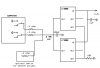
Originally I intended to replace 1 solenoid with the possibility of replacing 3. The original solenoids measure about 25 ohms....at 12 to 13.8Vdc (car voltage) a 25 ohm resistors (replacement solenoid) would need to dissipate about 12 watts. I came up with a better (I think anyway but who am I to say that) way to do this...the computer applies a ground to the solenoids and checks that approx 1/2 an amp is being used (better way of saying that Im sure)...with the attached schematic I came up with I would only need 1/4 watt, .4 ohm resistors and still achieve the desired 1/2 amp requirement the computer is looking for....this has to be better than the way I was planning on....Three 50 watt, aluminum housed, 25 ohm'ers.
 

Attachments

  • 3080f.pdf
    292.3 KB · Views: 184
  • possible.PNG
    possible.PNG
    38.1 KB · Views: 161
Last edited:
13.8v into 25 ohms is 0.552 amps but the resistor will only dissipate 7.6 watts. I don't know where you got your 12 watts from.

If you use a different type of load then you will still be dissipating 7.6 watts - it has to go somewhere.

The IC you put a datasheet up is a low dropout voltage regulator - are you going to just short this out or feed the .4 ohm resistors ? Whichever way you do it, you're going to have this 7.6 watts power to dissipate - if you use the regulator then it will have to dissipate this power and use a heatsink.
 
13.8v into 25 ohms is 0.552 amps but the resistor will only dissipate 7.6 watts. I don't know where you got your 12 watts from.

OOPS! Your correct...I was just working on another project which uses a 12.5 ohm solenoid...got my numbers mixed up :)

The idea idea came from how the computer knows whats a good or bad solenoid...it measures current draw...which for a 25 ohm solenoid would be anywhere from .48 to .552A (thanks again for the correction) at 12-13.8vdc (car voltage)

So instead of connecting 25 ohm resistors and having to dissipate 7.6 watts each...(keep in mind I might need to trick 1 other similar solenoids which makes it almost 23 watts total :eek:) I would replace the solenoids with 2 of those voltage regulators in parallel to give me 2A output. Then use two (possibly three) 1/4 watt, .4 ohm resistors. When the computer grounds the new resistors it will still read a .5A current draw but each resistor will only dissipate .1 watts.

It makes perfect sense but while the resistors are not dissipating much I know that these voltage regulators are. I don't know enough to be able to take all the graphs in the data sheet and figure it out.

In operation all three solenoids (resistors) would never be on at the same time....either one,two or none but never all three. I could probably get away with a single voltage regulator but 2 in parallel helps spread the heat and if for some reason the computer malfunctioned and all three were on it can't hurt. So normally there would be a requirement for only .5A with one resistors or 1A for two to be shared between two regulators (or a max of about .5A each)

There must also be some heat involved with the switching of 12Vdc down to .2Vdc but again I dont know enough to be able to figure that out..any help appreciated!
 
Last edited:
You're missing the point. If you don't dissipate the 7.6w in the resistors it will be dissipated by the regulator.

You are going to need to get rid of 7.6W of heat whichever way you decide to do this.

Without very good heatsinking on the regulators you're going to fry them in a matter of seconds.
 
ok...I understand better now...is that because no matter what I do I will (in this case) always have a starting voltage of 12VDC? and because I always need to get to .5A it will always dissipate 7.6 watts? I just choose where I want 7.6 watts to go...which I guess would mean the resistors are the superior choice. It also makes the project easier in the long run. thanks for the valuable info!
 
Yup - you've got it :)

You could convert it into movement with a motor but there will still be heat generated.
You could convert it into light with a bulb but it will still heat up 7.6 watts
You could (theoretically) convert it to pure light with a 100% efficient LED but that light would have to go somewhere and at 7.6W would be capable of burning
You could convert it into sound but you'd get a headache.

Talking of headaches, getting rid of excess power/heat is one of the banes of my life when I'm designing stuff for cars.
 
Status
Not open for further replies.

Latest threads

Back
Top