Continue to Site

Welcome to our site!

Electro Tech is an online community (with over 170,000 members) who enjoy talking about and building electronic circuits, projects and gadgets. To participate you need to register. Registration is free. Click here to register now.

  • Welcome to our site! Electro Tech is an online community (with over 170,000 members) who enjoy talking about and building electronic circuits, projects and gadgets. To participate you need to register. Registration is free. Click here to register now.

Trigger Circuit Output Problem

Status
Not open for further replies.

cloakinghalk

New Member
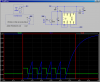
I have a circuit that is being used to trigger a camera to take a picture using a photo resister. The circuit is supposed to output 5 volts to the camera whenever a laser hits the photo resister. The circuit works perfectly when the camera is not plugged into the circuit but when it is plugged in, the voltage drops to about 1V. Can anyone explain why this is happening and how I can fix it?
 
Its not working under load.
Did it ever work?
Do you have a schematic?
What camera?
 
The photo resistor should probably drive a transistor which would trigger the camera signal. Photo resistors almost never directly drive anything.
 
I originally posted here and recieved a schematic for a circuit that would trigger by a hall sensor (by MikeMl). The attached image is the circuit he provided. I modified this circuit to use a photoresister intead of the hall sensor because the hall sensor caused mechanical issues. The power supply is a kit a freind of mine bought that took a 9volt battery and converted it to a regulated 5 volts. I cannot seem to find the kit online anymore but I can continue to look if needed. I am triggering a TSI Synchronizer Model 610034 which then triggers a highspeed camera. I cannot remember whether the circuit worked before with this synchronizer but it does work with a different model Synchronizer I have. For this synchronizer the voltage also drops but only to about 4.3V. This is enough to trigger the synchronizer.
 

Attachments

  • DF59.png
    DF59.png
    41.3 KB · Views: 144
On average a 9 volt rectangular battery (PP3) is about a 400 to 550 mAh battery depending on composition like Zinc Carbon or Alkaline. The 5 volt kit you mention was likely no more than a LM7805 voltage regulator and a few caps. Another would be easy to assemble. The normal or typical drain on a PP3 battery is about 15 mA. Since you mention the voltage drop my guess is something is loading things down. The 555 can source 200 mA. Would there be any possibility you have the polarity reversed going to the camera? The circuit works fine sans camera, you connect the camera and the voltage drops to a volt? I would bet the thing is being loaded. Just a guess on my part...

Ron
 
I am triggering a TSI Synchronizer Model 610034 which then triggers a highspeed camera.
It would help if you could get hold of a schematic for that unit. There is clearly a polarity or impedance issue with driving that.
 
@Ron I will check on Monday when I get back from vacation. I am pretty sure the polarity is correct but I will check just to make sure since other people have touched the circuit after I built it. Are you also trying to say that the 9 volt battery is not supplying enough current?

@Alec There are no schematics of the synchronizer that I can find. I will look some more and call the company to see what they can provide me with. The files I have on the unit barely even discuss anything technical about the unit. It is more a how to plug everything in and get it working document.
 
I see from the blurb for that synchroniser that it can be triggered by a TTL signal. So the photo-sensor signal needs to be converted to a signal that switches between 0 and +5V with a source impedance < 1k or so.
 
Thank you everyone, it turned out that the polarity was reversed. The person that used the trigger after me labeled the connecting wires wrong. It works perfect now. Thanks.
 
Glad it is working.

Ron
 
Status
Not open for further replies.

Latest threads

New Articles From Microcontroller Tips

Back
Top