Continue to Site

Welcome to our site!

Electro Tech is an online community (with over 170,000 members) who enjoy talking about and building electronic circuits, projects and gadgets. To participate you need to register. Registration is free. Click here to register now.

  • Welcome to our site! Electro Tech is an online community (with over 170,000 members) who enjoy talking about and building electronic circuits, projects and gadgets. To participate you need to register. Registration is free. Click here to register now.

Trouble with Schaer+ programmer

Status
Not open for further replies.

AndrewR

New Member
Hello 2 all ! First off all i have to mention that i am trying to program a pic18f452 microcontroller. I've made on a pcb the "wonderfull" schaer+ programmer and i have obtained corect Vpp and Vcc voltages. Still, i can't program the PIC. The hardware is detected by the PP18 software which and i'm using the correct dll.

Now...my question is: why doesn't the software+programmer recognize my microcontroller ? The microcontroller has never been used and i've measured carefully the voltages before inserting it into the programmer.
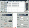
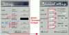
What are the corect settings in the PP18 software ?

Thank you very much !

P.S.: I've read the DS39531A document from Microchip concerning ICSP techinique.
 
Hi,

Haven't used the Schaer programmer and PP18 software, but it looks the same as a standard P16PRO40 as mentioned many times in this forum.

Have a quick search / look - should be some useful info.

Have you tried running it with the WinPic or WinPicProg free software - they also allow you to test each data lines, not just the power rails.
 
In the original design, there is a LED on the VPP line.

Does the LED flash at about 0.5 seconds interval? It flashes even if no PIC is detected.

I have attached an image from my own PP18 programmer. However, the pin names on the lower right is totally different from the Schaer+ design as I have moved signals around to suit my other needs.

Do not use them. !!!!

Basically that is all one need to change to get the programmer to recognize a PIC. I will follow up this post with a proper one after I studied the Schaer+ schematic.
 

Attachments

  • PP18_Setup_BAD.gif
    PP18_Setup_BAD.gif
    43.6 KB · Views: 191
eblc1388 said:
In the original design, there is a LED on the VPP line.

Does the LED flash at about 0.5 seconds interval? It flashes even if no PIC is detected.

I have attached an image from my own PP18 programmer. However, the pin names on the lower right is totally different from the Schaer+ design as I have moved signals around to suit my other needs.

Do not use them. !!!!

Basically that is all one need to change to get the programmer to recognize a PIC. I will follow up this post with a proper one after I studied the Schaer+ schematic.

Thank you for the quick response. YES the LED flashes 2 times/second. I'll try next to raise the Vpp to 13 V. Maybe this is the problem. And another problem might be those pin name notations in the pp18 software. Need help in figuring them out.:confused:
 
I have done checking the circuit.

The correct setting for the original Schaer+ schematic design is attached.

CMD_3 is ERROR
CMD_4 is SELECT
CMD_5 is PAPER OUT
CMD_6 is ACK
CMD_7 is BUSY
 

Attachments

  • PP18_OK.gif
    PP18_OK.gif
    21.3 KB · Views: 167
Status
Not open for further replies.

Latest threads

New Articles From Microcontroller Tips

Back
Top