Continue to Site

Welcome to our site!

Electro Tech is an online community (with over 170,000 members) who enjoy talking about and building electronic circuits, projects and gadgets. To participate you need to register. Registration is free. Click here to register now.

  • Welcome to our site! Electro Tech is an online community (with over 170,000 members) who enjoy talking about and building electronic circuits, projects and gadgets. To participate you need to register. Registration is free. Click here to register now.

Variable Freq Oscillator

Status
Not open for further replies.

forever99482

New Member
Hi, I've got a question about the circuit below

**broken link removed**

As it is using a TCA440, the oscillator and mixer is actually in it, and I cannot test to see the output from the Variable Freq Oscillator(kank3333r part), any ideas of how I could test to see the output of the VFO is correct?

By the way, can anyone find the datasheet of kank3333r?? I googled it and can't seem to find the datasheet of it.

Thanks in advance
 
Hi Forever99482,

You can try to measure at pin 5 of the TCA440.

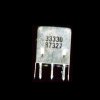
Data for the BKANK3333R :

between pins 1 and 2 14 turns
between pins 2 and 3 41 turns
between pins 1 and 3 55 turns
between pins 4 and 6 14 turns, pin 5 is not connected !

Inductance 45 µH, Q = 60 probably measured between pins 1 and 3.

on1aag.
 
on1aag said:
pin 5 is not connected !
on1aag.

pin 5(toko) is not connected?? but the circuit shows that it is connected to pin 5 of tca440. Please explain a bit more, I might be confused.

some more questions,
1. what frequency should I be looking at before the input to the lm386 (pin 3)?
2. What frequency should I be expecting on the mixer output of tca440, as I'm seeing frequency as high as 100MHz.....

Thank you :)
 
Last edited:
forever99482 said:
pin 5(toko) is not connected?? but the circuit shows that it is connected to pin 5 of tca440. Please explain a bit more, I might be confused.

some more questions,
1. what frequency should I be looking at before the input to the lm386 (pin 3)?
2. What frequency should I be expecting on the mixer output of tca440, as I'm seeing frequency as high as 100MHz.....

Thank you :)

1. Audio frequencies only, as this is after the signal has been detected and filtered by the detector diodes, for AM audio modulation content only.

2. 455khz that then feeds to the ceramic IF 455khz filter to remove any other mixer products.

Your local osillator will have to cover a 3.045 to 3.545mhz range to convert the 3.5-4mhz ham 80 meter band to the 455khz IF frequency of this design.

Lefty
 
As I'm not inputing any RF signals to it, so shouldn't the mixer output be around 3.5MHz? Unless my VFO is not working correctly....
 
forever99482 said:
As I'm not inputing any RF signals to it, so shouldn't the mixer output be around 3.5MHz? Unless my VFO is not working correctly....

Most mixer designs use a balanced mixer that only outputs the sum or difference between RF and LO. If no RF or no LO then there would be no mixer output at all. You can normally not troubleshoot mixer problems easily without a spectrum analyzer.

Lefty
 
Hi Forever99482,

The pin 5 mystery is only a typo that probably sneeked in because
pin 6 of the KANK3333R is connected to pin 5 of the TCA440.
As with most Toko 10K coils pin 5 is missing, so it can't be connected
to pin 5 ! The general rule is if it isn't necessary pin 5 is always
missing, the same goes for KANK3334R, KANK3335R and a lot of other
Toko coils.

on1aag.
 

Attachments

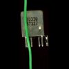
  • kank3333r.jpg
    kank3333r.jpg
    54.1 KB · Views: 636
  • kank3333r  wire.jpg
    kank3333r wire.jpg
    53.7 KB · Views: 537
  • kank3333r  bottom.jpg
    kank3333r bottom.jpg
    61.2 KB · Views: 559
about the trimmer cap in the VFO part, is it used for impedance matching with the toko?

What frequency should I be looking at for pin4,5 and 6 of TCA440 with an AM modulated sinewave of 3.5MHz fed in to pin1/2 of the TCA440
 
Last edited:
Hi Forever99482,

The trimmer cap C11 is used to set the frequency of the local oscillator
that it will cover the 80 m band.
It has nothing to do with impedance matching.
The signal measured at pins 4,5 and 6 will always be the oscillator
frequency no matter what signal you apply to the inputs of the TCA440.
I've checked the internal circuitry of the TCA440 and pins 4 and 5 are
differential inputs, pin 6 is the open collector output of the oscillator.
Try to measure the signal at pin 6 of the TCA440.
Make sure you haven't mixed up the connections of the KANK3333R,
I measure 0,7 :eek:hm: between pins 1 and 2
and 1,9 :eek:hm: between pins 2 and 3 which seems to agree with
the schematic.
The Toko catalogue doesn't give a specific footprint for the KANK3333R
but from what I can measure I think that the pins are numbered like
integrated circuits.

on1aag.
 
tca440 oscillator

Hello,
Can anybody please help me out with oscillator configuration of the tca440.
the internal oscillator circuit can be controlled by pin 4 5 and 6. my questions are

1) how do you control the frequency of the signal produced by this internal oscillator by using this three pins?

2) am i suppose to build a whole new oscillator circuit to control the internal one?

3) how do i build an oscillator circuit that controls another oscillator circuit?

Thanking you i advance
 
electrocompo said:
Hello,
Can anybody please help me out with oscillator configuration of the tca440.
the internal oscillator circuit can be controlled by pin 4 5 and 6. my questions are

1) how do you control the frequency of the signal produced by this internal oscillator by using this three pins?

2) am i suppose to build a whole new oscillator circuit to control the internal one?

3) how do i build an oscillator circuit that controls another oscillator circuit?

Thanking you i advance

You use a tuned circuit to set the frequency, like almost every RF oscillator there is - it's clearly shown on the diagram above.
 
Thanks for the reply!

the oscillator circuit above is just too confusing (I'm kind of new to this.. ).

So there are many kinds of RF oscillator that I can use with the tca440?
Arent RF oscillator meant to be connected to the mixer directly... I mean if it is an RF oscillator and we are connecting it to another oscillator (the internal one) then its like two oscillator connected together? does that make sense?

I really need help with this topic
 
Hi Electrocompo,

electrocompo said:
So there are many kinds of RF oscillator that I can use with the tca440?
Arent RF oscillator meant to be connected to the mixer directly... I mean if it is an RF oscillator and we are connecting it to another oscillator (the internal one) then its like two oscillator connected together? does that make sense?

I really need help with this topic

The TCA440 is a single chip single conversion AM receiver.
All active components are inside the chip and the oscillator
is allready connected to the mixer. Only the frequency dependant
components are external.

https://www.alldatasheet.com/view.jsp?Searchword=TCA440

on1aag.
 
electrocompo said:
So there are many kinds of RF oscillator that I can use with the tca440?
Arent RF oscillator meant to be connected to the mixer directly... I mean if it is an RF oscillator and we are connecting it to another oscillator (the internal one) then its like two oscillator connected together? does that make sense?

Like on1aag says, there's only one oscillator circuit there, with the active part inside the chip, and the LC tuning part outside the chip - two halves make a whole.

You're making it far more complicated than it is!.
 
forever99482 said:
pin 5(toko) is not connected?? but the circuit shows that it is connected to pin 5 of tca440. Please explain a bit more, I might be confused.

some more questions,
1. what frequency should I be looking at before the input to the lm386 (pin 3)?
2. What frequency should I be expecting on the mixer output of tca440, as I'm seeing frequency as high as 100MHz.....

Thank you :)

Hi Forever99482,

where did you get the TCA440 in Malaysia and at what price-- as I need few pieces for a friend in Malaysia. plse try to give shot contact if you had purchase recently sir
 
TCA440 Oscillator Circuit

Nigel Goodwin said:
Like on1aag says, there's only one oscillator circuit there, with the active part inside the chip, and the LC tuning part outside the chip - two halves make a whole.

You're making it far more complicated than it is!.


Thanks for your help!... really appreciate it.

But just one more thing: about the "LC tuning part" outside chip as you mentioned above,

Is that the only configuration (in the circuit diagram above) that can be used with the TCA440?

If yes, how does this oscillator circuit works as there are both "trimmer capacitor" and "variable resistor" in the circuit. i would just like to know the separate function of this components cos i understand one of them is definitely responsible for tuning the circuit.

If there are other cofiguration out there, could you please point me in the right direction?

Also, could you please tell me the exact relationship between the internal osccillator (the 1st half) and the external oscillator (the second half). I mean do i not need to know this reationship to understand how the external oscillator controls the internal one?
and the three pins of the intena oscillator...are those the "base", "emitter" and "collector" pins?

I do not mean to bug you guys but i really need help on this topic
Thanks in advance... hope u having a nice festive season!
 
Last edited:
electrocompo said:
Thanks for your help!... really appreciate it.

But just one more thing: about the "LC tuning part" outside chip as you mentioned above,

Is that the only configuration (in the circuit diagram above) that can be used with the TCA440?

If yes, how does this oscillator circuit works as there are both "trimmer capacitor" and "variable resistor" in the circuit. i would just like to know the separate function of this components cos i understand one of them is definitely responsible for tuning the circuit.

If there are other configuration out there, could you please point me in the right direction?

Also, could you please tell me the exact relationship between the internal osccillator (the 1st half) and the external oscillator (the second half). I mean do i not need to know this reationship to understand how the external oscillator controls the internal one?
and the three pins of the intena oscillator...are those the "base", "emitter" and "collector" pins?

I do not mean to bug you guys but i really need help on this topic
Thanks in advance... hope u having a nice festive season!

If you recollect the normal Super-het radios, you will fine that there is a tunable coil, trimmer and also a variable capacitor with control knob given for the user. now, imagine the variable capacitor for user control is now upgraded by vari-cap and a pot to adjust its capacitance by the user.

Now to explain it, user wants a specific range of frequencies in the tuning range by the potentiometer. the adjustable slug of the coil and trimmer help the manufacturer or the designer, to set this range. In actual practice, the user doesn't fiddle with the coil or the trimmer.

Hope I am clear to you. all the best and Merry Christmas
 
Last edited:
Thanks for your help!

so after building the ciruit above all i need to do to adjust the oscillator frequency is fiddle with the potmeter?

Just wanna clarify some points here:

I wanna use this to work with RF signals within the range 3.5MHz - 3.6MHz with 455KHz as the IF frequency.

1) What frequency should i set the oscillator frequency to?
2) Since there is no indicator or some kind of visual user interface for the oscillator, how do i check if the desired oscillator frequency have been achieved?
3) Also, as I have no real RF signals and I can only test this circuit in the lab. do u have an idea on how to go about simulating an RF signal within the range 3.5MHz - 3.6MHz and testing this circuit? i intend to use an oscilloscope to check the corresponding outut and not the audio aids as i am focusing on the front part of the circuit only.

Thank You.
 
electrocompo said:
Thanks for your help!

so after building the ciruit above all i need to do to adjust the oscillator frequency is fiddle with the potmeter?

Just wanna clarify some points here:

I wanna use this to work with RF signals within the range 3.5MHz - 3.6MHz with 455KHz as the IF frequency.

1) What frequency should i set the oscillator frequency to?
2) Since there is no indicator or some kind of visual user interface for the oscillator, how do i check if the desired oscillator frequency have been achieved?
3) Also, as I have no real RF signals and I can only test this circuit in the lab. do u have an idea on how to go about simulating an RF signal within the range 3.5MHz - 3.6MHz and testing this circuit? i intend to use an oscilloscope to check the corresponding outut and not the audio aids as i am focusing on the front part of the circuit only.

Thank You.
1. for LO to be on the High side- set it to 3.955 to 4.055MHz

2. the designer of this has made a calibrated scale on his RIGwitha pointer knob. It saves poer. you may however use a frequency counter- you may try out one by using PIC16f84 -try Google for IK3OIL frequency counter. He has given the circuit, pcb layout and also the hex file for the PIC ic. of course you need a PIC programmer. This frequency counter can be configured to have IF offset of 455 and set for Local oscillator on high side. it means the counter will read the value of antenna frequency directly by deducting 455KHz from the Local Oscillator frequency. you may go thro the article by IK3OIL.

3. you may use the laboratory test signal generator with 800 or 1000Hz audio tone with 30% AM Modulation setting.- while the RF can perhaps be at 3.57MHz.

Alternately you can use a crystal oscillator at 3.579545 MHz and it can be tracked on the receiver you are making. when you receive this signal at optimal tuning the audio will be almost silent., if mno modulating signal is there. other wise you hear the audio tone at minimum volume setting even

If you don't want to reach the audio point, you can measure the AGC voltage at the AGC pin of TCA440.-- but as i analyze, i could not trace the AGC from the detected output in the circuit under concern.
 
Last edited:
thank you very much!!! Finally I'm starting to make sense of this circuit.

i just seacrh on google for crystal oscillator n there are loads of them...some for some kinda clock counter and some for coverter or somethin like dat. My questions are

1) is there a particular type of crystal oscillator needed for the task at hand or do i need to design and build a circuit for this or can i just buy one?
if i can buy one..is there any speification i need to know about?

2) when uisng signal generator as u explained above, do i need to set both the "audio tone" and the "RF signal's frequency" or re they mutualy exclusive? (sorry I havent used one before...lol)

3) Also, i was talking to a friend and he said a crystl oscillator can aso be used as the external oscillator ciruit that controls the internal one... UR COMMENT ON THIS WILL BE GREATLY APPRECIATED!

Thanks
 
Status
Not open for further replies.

Latest threads

New Articles From Microcontroller Tips

Back
Top