I'm trying to fix a vehicle telematics unit.
What I think was a ceramic capacitor got damp and was damaged. I wasn't able to read any value from it. The circuit board near it got corroded as well.
I traced some of the circuit and it was connected to the mid point of two 4k7 resistors like this:-

I can't work out where the tracks go from there as it is a multilayer board and all the connections to the resistors go to vias and I can't see where they go as they don't go anywhere else on the top or bottom of the the board.
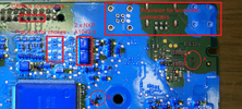
What is odd it the position on the board of the component that I think was a capacitor. Here is a photo of the board:-
 That was taken under UV light to show the conformal coating. The failed component was at point A, and the resistors that it connects to are at point B.
The conformal coating has been missed off where there are a test points that are needed after assembly, and that is what has let the moisture get to the failed component.
On both top and bottom of the board, there are spaces for components that are not populated near point A.
The conformal coating makes it difficult to trace continuity.
Does anyone have any idea why the failed component was places so far away from the resistors?
Should I just fit a 100 nF capacitor or are there any better suggestions?
What I think was a ceramic capacitor got damp and was damaged. I wasn't able to read any value from it. The circuit board near it got corroded as well.
I traced some of the circuit and it was connected to the mid point of two 4k7 resistors like this:-
I can't work out where the tracks go from there as it is a multilayer board and all the connections to the resistors go to vias and I can't see where they go as they don't go anywhere else on the top or bottom of the the board.
What is odd it the position on the board of the component that I think was a capacitor. Here is a photo of the board:-
The conformal coating has been missed off where there are a test points that are needed after assembly, and that is what has let the moisture get to the failed component.
On both top and bottom of the board, there are spaces for components that are not populated near point A.
The conformal coating makes it difficult to trace continuity.
Does anyone have any idea why the failed component was places so far away from the resistors?
Should I just fit a 100 nF capacitor or are there any better suggestions?