Continue to Site

Welcome to our site!

Electro Tech is an online community (with over 170,000 members) who enjoy talking about and building electronic circuits, projects and gadgets. To participate you need to register. Registration is free. Click here to register now.

  • Welcome to our site! Electro Tech is an online community (with over 170,000 members) who enjoy talking about and building electronic circuits, projects and gadgets. To participate you need to register. Registration is free. Click here to register now.

What is this electronic device???

Status
Not open for further replies.

gary350

Well-Known Member
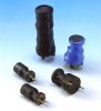
I unsoldered this from a circuit board. It has a perment magnet on top. At first I thought it was some type of choke coil but now I see + on one wire and - on the other wire. I have never seen a choke with polarity. It does not appear to be a capacitor but who knows. I did a search and nothing comes up.

Part number 361678-2 REV. J8242 TDK TWN

What is it??????

**broken link removed**

**broken link removed**
 
Last edited:
Rather does look like a capacitor. But I have no idea why it would have a magnet attached.
 
I too have scavenged a few of those and wondered about the usage of the magnet.

Removing the heat-shrink simply reveals a ferrite core and a coil, topped with a magnet.

It would be interesting if someone could shed some light on the reason for the magnet being there...
 
Possibly a speed pickup? But I am not sure why the ferrite core as a speed pickup would generally have an iron core topped with a magnet. Also, never saw a speed pickup labeled with polarity.

Ron
 
Last edited:
One use is to adjust the response of deflection coils in TV's and monitors.

Interesting aside, electric guitar enthusiasts will be aware of an effects pedal called the "Dunlop Crybaby". At one stage of their manufacture they used a cheaper coil with a core that actually took on a magnetic field, affecting them in the same way as the device you have. The different sound was so well recieved by the buyers that the defective coil is now a special option that costs $$$ more.
 
Yes it probably was used in a horizontal deflection circuit in a TV or monitor.
The magnet biases the ferrite core to one side. With out the magnet the core will work from +4 to –4 amps. With the magnet it might work from 0 to 8 amps. Other than in horizontal deflection, I have used these to filter DC supplies, where I know the current will always be in the same direction.
 

Attachments

  • linearitycoil.jpg
    linearitycoil.jpg
    25.6 KB · Views: 197
I have a handful of these in my bits box, I yank them out of power supplies generally.
 
Yes it probably was used in a horizontal deflection circuit in a TV or monitor.
The magnet biases the ferrite core to one side. With out the magnet the core will work from +4 to –4 amps. With the magnet it might work from 0 to 8 amps. Other than in horizontal deflection, I have used these to filter DC supplies, where I know the current will always be in the same direction.

That's what I thought.


It's effectively a polarised inductor. Adding the magnet doubles the current rating but polarises it so the inductor only works in one direction. You could probably do this with any inductor but the wire still needs to be thick enough to carry the current.

Surely this could also work in a flyback or buck regulator as the current only flows in one direction? I've never seen an polarised inductor used in that type of circuit before though.
 
It's very similar to the technique used in a common mode, or bifilar wound, choke to prevent saturation of the core. Minus the magnet.
 
Last edited:
My personal referance to such a device is the magnetic amplifiers or magnetic regulator circuits in the older style commercial welders.
In those applications the magnet would be and electromagnet coil so the inductor can be biased to have variable pass though of current and voltage in one direction and variable blocking ability's in the other direction.

Its also can be used as rather crude induction rectifier of sorts. I have seen a few references from the early 1900's to its use with the high power DC systems inner city public transport systems in different places around the world had back then. It was the closest competitor to the massively inefficient Mercury arc rectifier tubes and mechanical synchronous rotary converters of the day.
 
Is this how an AC arc welder is converted to DC? Lincoln sells an AC welder and for about $100 more you can buy a DC welder. I have always wondered if there is some way I could make my AC welder be DC. DC welds a lot nicer than AC.
 
The modern DC arc welder is basically just the AC arc welder with a high amp bridge rectifier with a big inductor in series with one of the output leads. Converting the more basic AC welders to be a DC one is fairly basic.

Four big high amp diodes and a homemade reactance coil made out of an old higher wattage microwave oven transformer or old HID light ballast will give you a surprisingly good DC conversion kit!

Although its not ideally matched to the original AC welder transformer it will still give a good clean weld if done even half way right.

The most basic AC/DC multifunction welders just used a big DP3T switch to change the output from a tap on the AC right off the transformer to either DC+ or DC- taken from the output of the rectifiers and reactance coil.

I have loads of service manual files available for countless Lincoln, Miller, Century, Hobart and other brands of welders available if you need one for referance schematics.
 
Status
Not open for further replies.

Latest threads

New Articles From Microcontroller Tips

Back
Top