Mr RB
Well-Known Member
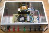
Hi, I'm making a 12v 4A automatic battery charger for my emergency power 12v car battery. I found an old 1970's linear regulated power supply in a nice metal box, with what looks like a 1970's or 60's transformer.
Originally I was going to make it as PWM (buck SMPS) voltage and current regulated, but testing the transformer showed it was very "soft" with a lot of voltage sag under current, so it looks like it was a transformer likely made for a TRIAC phase angle controlled battery charger, the transformer looks a bit older than the box so this is pretty likely.
The transformer size is 80-100W, and unreg DC is 21v no load and sags to 15v at 5A. I tested it loaded to supply 16v at 4A and temperature rise after a few hours was within reasonable limits so it should be fine for a 14.5v DC 4A max battery charger.")
Now the questions. It's going to have a PIC microcontroller using the ADC to regulate charging voltage and max current, and also to be an automatic "smart" charger, ie reduce from 14.5v to 13.8v after bulk charge is complete.
The main question is should I make it TRIAC phase angle controlled like a traditional 60's regulated battery charger, or possibly use a different regulation based on complete halfcycles? (please see diagram).
**broken link removed**
When I was an apprentice in the early 1980's the old guys in the workshop preferred to use the old TRIAC based battery chargers, they had the opinion that charging the battery with pulses of current gave a better result and/or some rejuvenating effect, compared to the newer fixed DC chargers.
I really don't want to start an argument about that point, so the purpose of the thread is really o discuss any issues with the two proposed methods of TRIAC voltage regulation, ie with regards to peak currents in the transformer or semis, and which might offer better reliability or better performance in some way.
The project is nearly completed and I will post photos etc on the forum in a few days. At this point it is working fine under PIC control and it's really just a software change now to change the method of TRIAC control.
Originally I was going to make it as PWM (buck SMPS) voltage and current regulated, but testing the transformer showed it was very "soft" with a lot of voltage sag under current, so it looks like it was a transformer likely made for a TRIAC phase angle controlled battery charger, the transformer looks a bit older than the box so this is pretty likely.
The transformer size is 80-100W, and unreg DC is 21v no load and sags to 15v at 5A. I tested it loaded to supply 16v at 4A and temperature rise after a few hours was within reasonable limits so it should be fine for a 14.5v DC 4A max battery charger.
Now the questions.
It's going to have a PIC microcontroller using the ADC to regulate charging voltage and max current, and also to be an automatic "smart" charger, ie reduce from 14.5v to 13.8v after bulk charge is complete.The main question is should I make it TRIAC phase angle controlled like a traditional 60's regulated battery charger, or possibly use a different regulation based on complete halfcycles? (please see diagram).
**broken link removed**
When I was an apprentice in the early 1980's the old guys in the workshop preferred to use the old TRIAC based battery chargers, they had the opinion that charging the battery with pulses of current gave a better result and/or some rejuvenating effect, compared to the newer fixed DC chargers.
I really don't want to start an argument about that point, so the purpose of the thread is really o discuss any issues with the two proposed methods of TRIAC voltage regulation, ie with regards to peak currents in the transformer or semis, and which might offer better reliability or better performance in some way.
The project is nearly completed and I will post photos etc on the forum in a few days. At this point it is working fine under PIC control and it's really just a software change now to change the method of TRIAC control.