Continue to Site

Welcome to our site!

Electro Tech is an online community (with over 170,000 members) who enjoy talking about and building electronic circuits, projects and gadgets. To participate you need to register. Registration is free. Click here to register now.

  • Welcome to our site! Electro Tech is an online community (with over 170,000 members) who enjoy talking about and building electronic circuits, projects and gadgets. To participate you need to register. Registration is free. Click here to register now.

Why does my simple rectified AC signal look like this?

Status
Not open for further replies.

Pavius

New Member
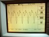
I've never worked with AC before, and after having rectified a simple 24VAC signal with a diode bridge (which looks like a perfect sine wave) i see this. Could it be the capacitance on the breadboard? The passive scope probes? The regulator and cap in the background are not connected in this case.

The signal gets filtered and regulated to 5V just fine, i'm just curious why it doesn't look like a perfect rectified sine wave.

TIA
 

Attachments

  • P1010179-large.jpg
    P1010179-large.jpg
    147.5 KB · Views: 238
  • P1010182-large.jpg
    P1010182-large.jpg
    124 KB · Views: 228
What does the AC waveform from the transformer look like? if similar spikes appear on both sides, (the positive and negative wave) I suggest it is mains carried interference.
If not it may just be one of the diodes damaged and causing it.
Nev.
 
put a load on ouput of rectifier and wave should be normal, this is probably cause by capacitance of oscilloscope
 
Also, make sure the X1/X10 switch on your scope probe is fully in one position or the other. In the photo it doesn't appear to be fully in the X10 position.

creakndale
 
Last edited:
When the transformer secondary voltage is at its peak, two diodes turn on, and one end of the winding is at about -0.6 V and the other end is at about 0.6 V above the capacitor voltage.

You have no load when you took those measurements, so the diodes are only turned on for tiny fraction of the period. The rest of the time, the voltage is free to float anywhere within the rectified voltage range, because the diodes are off. Then what you are seeing is stray capacitance from the primary side. If you touch the circuit, the waveform will change a lot.

If there is a load, then for a larger fraction of the waveform period, the diodes will be turned on, and the transformer voltage is fixed. However there will still be times when the diodes are off and voltage is floating.

This doesn't matter at all. Most rectified AC circuits are like that.
 
Hi PCBWING,

I haven't experienced any harmonics from 50 Hz mains voltage within 55 years. May be that has changed in some countries using nuclear powered generators.

My opinion about the displayed waveform:

a) a lousy quality oscilloscope :(
b) lousy copies of 1N4001 diodes :(
c) lousy arrangement on the breadboard :(

overall lousy: :mad:

Regards

Boncuk
 
Hi,

Could also be because of the differences in diode capacitance in the rectifier diodes. Try putting a small load on the output.
 
a) a lousy quality oscilloscope :(
>>> Tektronix :) with crappy 10$ passive probes :eek:
b) lousy copies of 1N4001 diodes :(
>>> Perhaps :eek:
c) lousy arrangement on the breadboard :(
>>> If I can't connect 4 diodes properly on a breadboard, i'd be better off killing myself :)

overall lousy: :mad:
>>> Sorry to disappoint :eek:

Once I put a load on the output, the signal rectified looks perfect. Diver300, I will try to wrap my head around your explanation. Thanks.
 
Please do not get excited, I watch the waveform is very regular, if it is the quality of cause of instability, it might be not so rule, I'm young, willing to learn more knowledge to the older generation. :)
 
When the sine wave AC power interference by high harmonic for voltage and current waveforms will be affected and distortion (harmonic distortion), the deformation wave after wave as distortion (Distorted Wave). Any distortion waves contain high harmonics, after careful analysis, these distortion waves by adding a number of different frequency sine wave is made.

I am speaking from the book, and I do not know right, can you provide a schematic? Also can you do your circuit simulation? To distinguish is the quality of components and equipment, or the circuit itself.
 
Status
Not open for further replies.

Latest threads

New Articles From Microcontroller Tips

Back
Top