Continue to Site

Welcome to our site!

Electro Tech is an online community (with over 170,000 members) who enjoy talking about and building electronic circuits, projects and gadgets. To participate you need to register. Registration is free. Click here to register now.

  • Welcome to our site! Electro Tech is an online community (with over 170,000 members) who enjoy talking about and building electronic circuits, projects and gadgets. To participate you need to register. Registration is free. Click here to register now.

Will this work? Proximity sensor based circuit

Status
Not open for further replies.

cosmonavt

Member
I want to make a simple circuit of a car that will stop when it is 10 cm from a wall.

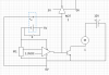
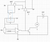
The motor M1 drives the car. The components highlighted in blue dotted rectangle is an optocoupler. The IR1 is the sensor located at the front of the car. When the object is far away, the sensor passes a very low voltage to the comparator. When it comes closer to the wall, this voltage increases. The 10cm equivalent of the sensor is 1.3V.

So when the switch X is briefly pressed, a P.D. is created across the sensor IR1 and the comparator. The sensor passes a voltage which is less than 1.3 and therefore, the comparator gives an output of 5V as well. Now this 5V is being supplied to the NOT1 gate which makes the output 0V and the NOT2 gate again makes it 5V. This 5V is now being passed into the same optocoupler which we bypassed earlier (by the switch) so the supply becomes constant and the switch need not be pressed.

Apart from NOT1 gate, the voltage passed on by the comparator also drives a transistor which amplifies it to 12V which will drive the motor. AS soon as the sensor voltage exceeds 1.3, the comparator will stop its output and the transistor (and hence the motor) will stop also. The power to the sensor and the comparator will be shutoff. Is this a correct circuit?
 

Attachments

  • 2982d1321036161-work-proximity-sensor-based-circuit-test-circuit.png
    2982d1321036161-work-proximity-sensor-based-circuit-test-circuit.png
    25.5 KB · Views: 301
The basic idea of the circuit should work. You need to connect the sensor to the -ve input of the comparator and the 1.3 V reference to the +ve input. You haven't labeled the inputs.

However, there are a few details that are wrong. The comparator output should have a resistor between it and the transistor, or the inverter (NOT gate) will never see a large enough voltage to work.

There should be a resistor between base and emitter of the transistor so that it doesn't turn on with the leakage current. You should also have a diode across the motor to stop inductive spikes killing the transistor.

Also, I don't think that it is a good idea to kill the output of the comparator that way, and it is over-complicated. Opto-isolators are used where you need isolation and you don't need that here. You could just connect the output of the second inverter to supply the comparator and the sensor.

Even better would be to supply just the 1.3 V reference from the output of the comparator. There would be no need for the inverters or the opto-isolator. When the comparator turns off, the reference goes low, so the comparator, and the motor, stay turned off.
 
First off, thanks a lot for the suggestions. Few questions though.

However, there are a few details that are wrong. The comparator output should have a resistor between it and the transistor, or the inverter (NOT gate) will never see a large enough voltage to work.
Well, I guess even if there is a resistor, the inverter will still see 5V.

There should be a resistor between base and emitter of the transistor so that it doesn't turn on with the leakage current.
Where does this leakage current come from? And I guess the transistors need 0.55-0.85V at least to turn on.

You should also have a diode across the motor to stop inductive spikes killing the transistor.
You totally lost me over here.

Also, I don't think that it is a good idea to kill the output of the comparator that way, and it is over-complicated. Opto-isolators are used where you need isolation and you don't need that here. You could just connect the output of the second inverter to supply the comparator and the sensor.
I totally agree. Actually the two inverters are redundant. See the new diagram that I made.

Even better would be to supply just the 1.3 V reference from the output of the comparator. There would be no need for the inverters or the opto-isolator. When the comparator turns off, the reference goes low, so the comparator, and the motor, stay turned off.
I am using LM339 which needs at least 5V per comparator, and if I do that, how will I start the circuit? :) Initially there is no power to the comparator, so no output. I need some initial voltage to trigger on the circuit.
 

Attachments

  • Capture.PNG
    Capture.PNG
    23.8 KB · Views: 144
Last edited:
You've not got a resistor between the output of the comparator and the base of the transistor. The base - emitter junction of the transistor will stop the output of the comparator getting above 0.8 V or so, which will make if difficult for the comparator to drive anything else.

Depending on what comparator you use, the output might be well below 0.5 V when it is low. If not, then another resistor between the base and ground would be a good idea. Either way, it can't hurt. I've just had to repair an amplifier where the clipping lights were glowing all the time because the manufacturer has left out the base - emitter resistors.

The diode that should be across the motor is called a freewheel diode. You can google that if you want. Without it, you risk inductive spikes damaging the transistor.

You won't get enough current from the opto isolator to power the comparator. Leave the comparator powered all the time, and feed the 1.3 V reference from two diodes. One diode to let power come from the comparator output, and one to let power come from the push button.
 
OK, and what about the rest of the circuit? Also, will this arrangement ensure that when the car reacher 10cm distance,

1. the sensor should turn off
2. The reference voltage should become zero
3. The sensor voltage should become zero
4. There should be no movement when the wall is moved further from the car

?
 
You can't connect the output of the comparator directly to the base of the transistor, because the base of the transistor cannot get to a larger voltage than 0.8 V or so.

You don't want the sensor voltage to drop to zero when the car is closer than 10 cm. You should only have the the reference drop to zero.
 
OK since I have to develop the circuit over further, it is my requirement to have the comparator and IR switched off when the car reaches 10cm distance so as per your suggestions, I have made a new block diagram. Two questions:

1. Will this work?
2. Is there a problem with two different batteries having interconnected ground (highlighted in red)?
 

Attachments

  • Capture.PNG
    Capture.PNG
    31.5 KB · Views: 139
Status
Not open for further replies.

Latest threads

New Articles From Microcontroller Tips

Back
Top