Continue to Site

Welcome to our site!

Electro Tech is an online community (with over 170,000 members) who enjoy talking about and building electronic circuits, projects and gadgets. To participate you need to register. Registration is free. Click here to register now.

  • Welcome to our site! Electro Tech is an online community (with over 170,000 members) who enjoy talking about and building electronic circuits, projects and gadgets. To participate you need to register. Registration is free. Click here to register now.

Is it possible to make a gate level digital wrist watch

Fluffyboii

Active Member
Hi,
Ever since I designed and simulated a digital watch with logic gates for one of my electronics classes in university I had this urge to take that design and make it reality with only transistors. Not even logic gates or flip flops. I did find that it is already done my different individuals and it is not an easy feat.

Anyway I am super into digital watches for the past year or so. I simply like telling the precise time at a simple glance and I love the unusual shape and sizes some digital watches have. Today the idea of making my own digital wrist watch got stuck on my mind. Obviously the easiest way to do it would be to get a microprocessor, few small 8 bit displays, rtc module for precise time keeping, slamming all of that in a 3d printed case. Even doing that would be a feat in itself.
Unfortunately using something like an Arduino, taking the Atmega something processor from it feels wrong. People make smartwatches with lots of functionality with those and just simple time keeping with it would make me sad. I could get a less powerful microprocessor and try to code in assembly to torture myself but I am not in that mood.
Using transistor level logic would never fit in a wrist watch form factor, I wonder if using smd versions of logic gate chips, flip flops, multiplexers, etc. would make it possible to fit in a wrist watch or do I need to get counter ICs and other more complex ICs for it to fit. Today most wrist watches that are digital have a small mcu, a quartz crystal with an inductor, few caps and resistors and thats it. Pretty boring and unrepairable.

I am also curious about when something stops being analog. Analog circuits are fascinating. I also want to make a calculator with all solid state components but analog in design. Adding and subtracting with op amps is easy enough but multiplication is difficult :( Obviously having it all solid state requires using some kind if led display which requires a dac at some point. Can something similar be done with a watch, nearly fully analog except the display. This is bit off topic from my initial wrist watch idea but is it possible to make a watch with a led display that does all the time keeping with an analog circuitry, just for the sake of it. Something like a RC circuit that charges a capacitor until a voltage threshold is passed that the triggers a comparator for example to keep time. I never truly understood when some circuit truly becomes digital.

This is just my random thoughts at 5am.
Edit: I just searched bit more and a microprocessor less watch requires immense amount of logic elements just as I remember that will definitely not fit in a small package unless I use ICs to do most of the hard work.
 
Last edited:
Hi,
I bought different LCDs to experiment with, on post #39 you can see them but links seem to be broken. I bought a selection of them with the smallest one this:
View attachment 145402
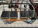
I am thinking of using the big 7 segment direct drive displays (4 of them) to make a large clock without any size restrains. One 4 digit 7 segment display I bought is 3cm in length so it can be used for a wrist watch, albeit a bit bulky one. I have 2 of those very small 2 digit ones and 2 of 3 digit ones in similar size. Unfortunately, there is no 4 digit 7 segment displays with that digit size.

Maybe for the time drifting issue, a temperature sensor can be thermal glued to the quartz to write a code specially to take the temperature in consideration. It could sample the temperature in intervals from something like LM35 to keep the power usage low. To be honest I am not sure if all of this can be fitted inside a nice to wear wrist watch sized package but I will try if I can get a big one functioning first.

Hi,

There are so many pitfalls when trying to roll your own RTC. The main problems are:
1. The time it takes to calibrate.
2. What else happens that you did not consider, then have to start all over again with the calibration.

There is a lot that gets in the way, such as the accuracy of the time measurements during calibration.
For example, if you wanted to check the calibration after one hour and ensure 5 seconds per year stability, you'd have to measure the time with a good existing clock down to about 500 microseconds. If you try to go lower you have to increase the accuracy of the comparison to the existing clock, and assume that the existing clock is not drifting up and down also.

All the problems means it takes a long time just to figure out what you have to modify when it doesnt seem to be working right.
Another problem is thermal gradients. It's hard to measure something when the sensor is any distance from the object being measured because if there is a temperature gradient it's not going to be constant and that means the measurement is not always going to be accurate. You'd have to encase the thing in a well insulated package to start.

Because of all this it makes sense to go with something already built. You get good one year stability with almost no trouble at all. That's hard to match.

If you only want maybe 10 seconds per week you might do it, but you would have to reset the clock every week.

If you do try and roll your own, let us know how you make out. It's always interesting to hear about these projects.
 
It could be interesting to have an output at one of the common mechanical watch beat rates, that could be connected to a piezo or tiny speaker & put that in a timegrapher?

If that worked, you can get a near instant readout of seconds per day accuracy.

The display is something like a scanned emulation of a stroboscope timing system, with the "drift" traced along the LCD, tick by tick.

There are also types for digital watches that allow a somewhat similar tuning of the crystal oscillator by monitoring the phase drift.

watch-timegrapher-big-zero.jpg
 
Hi,
Yesterday I decided to add another screen to the counter, it is connected to the same segment pins with the other display but COM pin is connected to the COM1 instead of COM0. So with the Bias Mode set to 1/2 and the LCD MUX set to 1/2 it should work all right. Except it has these ghost segments randomly being lit on. Sometimes it looks all right but there are semi lit segments that randomly appear and disappear. I can not see a correlation with the semi lit segments and the fully lit segments so it appears random. I messed with the LCD registers and changed pretty much anything I could think of such as: Changing the power mode, changing contrast bits, changing LCD clock prescaler, changing Type A waveform to Type B.

I also tried pulling my breadboard wires and using jumpers separately in case the segments were capacitive coupling to each other but it did not change the behavior. There is my LCD setup function, full code is also attached:

void LCD_setup() {
LCDSE0 = 0xF9; // Enable SEG0 to SEG7 except SEG1,2 because they use RA6 and RA7 OSC pins
LCDSE1 = 0x03; //Enable SEG0 to SEG1
//LCDDATA0 = 0xF9;
LCDDATA0 = 0x00;
LCDDATA1 = 0x00;
LCDDATA3 = 0x00;
LCDDATA4 = 0x00;

LCDPS = 0x72; //1:2 Prescaler, Writing allowed, LCD active, 1/2 Bias mode, Type-A waveform
LCDCON = 0xC5; //LCD Driver enable, LCD in Sleep mode enable, LCD error disabled, Clock T1OSC, COM1/2
LCDREF = 0xA0; //LCD contrast is powered by VDD, internal LCD ref. enabled

LCDCST = 0x02; //set the contrast (does not really change anything)
LCDRL = 0xA0; //Medium power mode for type A and B waveforms, no mode switching

//LCDPS = 0x32; //1:3 Prescaler, Writing allowed, LCD active, Static mode, Type-A waveform
//LCDCON = 0xC4; //LCD Driver enable, LCD in Sleep mode enable, LCD error disabled, Clock T1OSC, Static COM0
//LCDREF = 0x80;

//LCDCST = 0x07; //set min contrast
//LCDRL = 0xA0; //Medium power mode for type A and B waveforms, no mode switching
}
1715615319895.png

IMG_1991.jpg
IMG_1989.jpg
IMG_1990.jpg
7 and 6 looks okay for example but 7 and 1 has a lot of semi lit segments. The semi lit segments are the ones that are turned on both of the displays so it is not really a logical behavior.

Also is it possible to debug using PICkit2 Programmer software. Even the old MPLAB IDE does not support PICkit2 with the PIC16F1939 even though it is supported both in the datasheet and both in the software it refuses to let me use PICkit2 so I downloaded MPLAB X IDE v6.20 and load the hex. file I generate from there with the standalone PICkit2 Programmer software.
1715616144278.png

1715616255867.png
 

Attachments

  • LCD_Count0-99.txt
    7 KB · Views: 17
  • IMG_1988.jpg
    IMG_1988.jpg
    4.2 MB · Views: 18
Try setting bit 6 of LCDREF? That looks to reduce the drive to near 3V rather than 5V.

The voltage being too high could explain why the contrast control does not work??
 
Try setting bit 6 of LCDREF? That looks to reduce the drive to near 3V rather than 5V.

The voltage being too high could explain why the contrast control does not work??
I did try selecting the voltage reference * 3 FVR voltage as the contrast control and it did make me think it fixed the issue first but it did not. All it does severely reduce contrast by reducing the drive voltage to about 3V AC instead of 5V. The problem still remains but as the contrast is low so it gets hard to notice. Same with decreasing VDD itself. Lower than 4V VDD results in the same behavior. This LCDs do need bit more voltage than 3.3V to display properly. I think there is a programming issue, the way segments change makes me feel like it.
1715633769058.png

The issue is repeatable, the problematic number combinations are all the same. Maybe I should skip to driving 4 displays directly and see if it persists.

Everytime second it turns on the dot segment on one screen and turns it off for the other I can see the displays refresh and get more contrasty which is weird.

Another possibility is that these static displays are only meant to be used in static mode, but that does not make much sense and I can not drive 4 7 segment LCDs with 24 LCD pins of this MCU
 
Last edited:
Hi,

There are so many pitfalls when trying to roll your own RTC. The main problems are:
1. The time it takes to calibrate.
2. What else happens that you did not consider, then have to start all over again with the calibration.

There is a lot that gets in the way, such as the accuracy of the time measurements during calibration.
For example, if you wanted to check the calibration after one hour and ensure 5 seconds per year stability, you'd have to measure the time with a good existing clock down to about 500 microseconds. If you try to go lower you have to increase the accuracy of the comparison to the existing clock, and assume that the existing clock is not drifting up and down also.

All the problems means it takes a long time just to figure out what you have to modify when it doesnt seem to be working right.
Another problem is thermal gradients. It's hard to measure something when the sensor is any distance from the object being measured because if there is a temperature gradient it's not going to be constant and that means the measurement is not always going to be accurate. You'd have to encase the thing in a well insulated package to start.

Because of all this it makes sense to go with something already built. You get good one year stability with almost no trouble at all. That's hard to match.

If you only want maybe 10 seconds per week you might do it, but you would have to reset the clock every week.

If you do try and roll your own, let us know how you make out. It's always interesting to hear about these projects.
I was thinking using thermal epoxy to glue a temperature sensor to the quartz crystal directly. And I would let the clock run for a long time to measure the inaccuracy. Obviously it would take a long time to get a meaningful measurement. I can not really know the function of the quartz temperature frequency drift even if I know the temperature and there is also the quartz aging changing the frequency and the overall inaccuracy of the crystal itself, it will also change with the battery voltage going low as well.

My goal is beating my Casio fw-91 which skips 1 second in every 2 weeks. All other digital watches I own are considerably worse. Since my accuracy goal is not very extreme maybe it would be possible to just put a adjustable capacitor from ground to the quartz crystal and load the crystal directly to pull the frequency down or decrease the load to increase its frequency instead of going to the digital compensation route.

By the way there is this person who made a very efficient clock, not to far off what I want to do and the PIC is almost the same model as well:

He is using RTC module RV-3028-C7 but for utilizing the clock signal to drive the Gate inputs of the Timer1. Apparently it also consumes less power than using a quartz crystal with Timer1 and it is more accurate as well 1ppm.

I can not make a clock more efficient than his because I am using PIC16F1939 instead of PICLF1939 and my PIC has an inefficient linear voltage converter. Also my LCDs do not work at voltages as low as 1.8V. Also he is driving his LCDs in Static mode specially to save power but 1939 does not have enough pins to drive even 4x 7 segment LCDs, unless I do some wonky digital logic IC stuff which would probably neutralize the power savings that come from using Static drive.

I do have a DS3231M RTC module by the way. It just feels like cheating. One can always to this with like 50 lines of code using arduino libraries but it is not really meningful.
1715656023388.png
 
Last edited:
The issue is repeatable, the problematic number combinations are all the same. Maybe I should skip to driving 4 displays directly and see if it persists.

OK, then it's likely down to the LCD driver not being designed to drive separate displays. The voltages are presumably optimised for a one-piece display with all the commons interacting with the shared segments.
 
OK, then it's likely down to the LCD driver not being designed to drive separate displays. The voltages are presumably optimised for a one-piece display with all the commons interacting with the shared segments.
It may be the case. I will try to drive one of the multiplexed displays I have and if that works fine with similar configuration I will have to find another way to drive the large Static ones.

I would need PIC16F1907 to have enough pins to drive 4x 7 segment displays or 1947. I would rather not buy another PIC at this point. 16F1939 can drive 24 segments and I need 32 to drive my seven segment displays with the dots so they are technically 8 segments. 28 if you ignore the dots. Most left display will be 0, 1 or 2 so connecting A, D, E segments is possible. Would still need 27 segment pins.

I could use the SMD PIC16F1936 I have as a slave to drive more Static segments I guess but using two microcontrollers for a simple clock is way too silly. I also have a SMD 16F1939 as well as the DIP one. My intension was to use the 16F1936 for a wearable watch as 16F1939 has too many pins.
If I can not MUX drive separate LCD glass without glitching, that pretty much ruins my idea of a watch with multiple LCD panels such as the small 3 digit 7 segment ones. I need to experiment more…
 
Last edited:
I do not know anything about PIC programming, seems like the go to option for programmer is pickit3 or 2. There is PIC K150 for much cheaper than those but seems like it wont program the PIC you mentioned. I also want to ask, is it worth it to learn using these when everyone is using AVR microprocessors that are more powerful and probably documented better.
View attachment 145255
I wish they still made this type of displays. I could probably find another calculator like this to steal the displays but it would be better to find something that is new.

I finally found some 0.2 inc LED displays for sale. Quite pricey though.

There are few cheap clock kits sold on Aliexpress that use AT89C2051. I wonder why they use that specific microprocessor.

Check PICkit4
 
Check PICkit4
For now I am using PICkit2 I borrowed from my EE Prof. If I need to switch to a newer PIC to have enough segment pins to drive my Static LCDs such as PIC16F1907 or 1947 the PICkit2 will not support it, then I may consider buying PICkit4 or 3.

It sucks that I can not drive Static LCDs in multiplexed mode to save pins. PIC16F1939 almost has enough segment pins to drive 4 digits but not enough.
 
OK, then it's likely down to the LCD driver not being designed to drive separate displays. The voltages are presumably optimised for a one-piece display with all the commons interacting with the shared segments.
I got great news. by setting the following registers like this:
LCDPS = 0x12; Setting LMUX to 1/3 Bias mode
LCDCON = 0xCF; Setting LMUX to 1/4 multiplex so all COM pins are used.
The problem is gone. I do not know why displays did not behave with 1/2 multiplex ratio, both 1/2 and 1/3 bias caused issues with 1/2 multiplex but 1/4 multiplex seems to be fine. I think maybe one or two combinations of numbers that still cause the appearance of ghosting but it is much rarer compared to before and nearly impossible to detect from the intended viewing angles.

I tried experimenting with LCD clock prescaler and seems like anything after1:4 causes visible flickering. Anything less than 1:2 causes to much power consumption and contrast decreases. Setting LCD power from LCDRL register to high from medium power does not really improve anything but low power is definitely not enough. LCDCST contrast register is set to maximum contrast for now.

I will draw a simple PCB to solder the 4 LCDs on since breadboard is getting messy.
 
Last edited:
It is quite strange. There are still segments that light up when they should not. Most obvious one is when 0 is displayed on the LCDs. The middle “g” segment lights up when it should not. But it is not obvious if you are looking directly to the LCD. If you look from an angle, the weird segment looks more obvious than the enabled segments.

I feel like it is good enough since in intended viewing angles the weird effect is not really noticeable but it does bother me. I wonder if there is any workaround with the code but I pretty much tried every LCD register configuration possible and this is as good as it gets.

Maybe I am just stupid. These have a viewing angle of 60 degrees and here I am looking them from the side when they are pointing up. The effect does not happen on Static drive though. Last image proves that.

There are two possibilities: This effect is either a byproduct of using multiplex LCD drive mode in general or it is happening because these LCDs are only meant to be driven in Static drive mode.

Either way the only solution is getting a PIC16F1947 which has enough segment pins to drive 6 digits on Single drive mode but it will require a newer PICkit to program and considering the price of the LCDs it is not worth buying a new PIC and a PICkit to use them. Or I will find a way to drive 4 LCDs in Static mode with the PIC16F1939. How can I reduce the required pin count. If I use any logic gate IC to pass the outputs of the PIC I will lose all contrast control.
 

Attachments

  • IMG_2013.jpeg
    IMG_2013.jpeg
    2.9 MB · Views: 13
  • IMG_2014.jpeg
    IMG_2014.jpeg
    2.8 MB · Views: 15
  • IMG_2010.jpeg
    IMG_2010.jpeg
    2.1 MB · Views: 14
  • IMG_2011.jpeg
    IMG_2011.jpeg
    2.7 MB · Views: 13
  • IMG_2016.jpeg
    IMG_2016.jpeg
    2.1 MB · Views: 14
  • IMG_2017.jpeg
    IMG_2017.jpeg
    1.8 MB · Views: 15
Last edited:
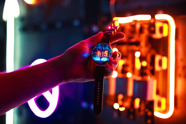
Don’t want to derail the thread, but I found that a few companies are actually selling NIXIE watches!
Pretty cool, I wish there was really small Nixie tubes so the watches themselves could be more wearable.
 
For now I have decided to move on to the smaller LCD displays. The 3 digit one works pretty well:
1715960911492.png

1715960926323.png


You can see the same effect where if you look at the LCD from an angle you can see unlit segments:

1715960960749.png

1715960974593.png


I believe this is the exact same thing that happens with the static LCDs when they are multiplexed but the effect more even since it is a single multiplexed LCD. Now I will try using multiple small LCDs at the same time by using more segment pins. If it works that way it means that I can make a sweet wristwatch with these guys. For the big LCDs I am not sure if I want to go with multiplexing since it decreases the quality of the image. Other options is to use PIC16F1936 as a slave to drive 2 of those large LCDs so 1939 can have 2 of them for itself.

Edit: Also got the 2 digit small display working:
1715983719521.png
 

Attachments

  • 3_segment_miniLCD_function.c
    6.5 KB · Views: 8
  • 2_segment_miniLCD_function.c
    4.8 KB · Views: 3
  • Small_LCDs_source.c
    16 KB · Views: 3
Last edited:

Latest threads

New Articles From Microcontroller Tips

Back
Top