Continue to Site

Welcome to our site!

Electro Tech is an online community (with over 170,000 members) who enjoy talking about and building electronic circuits, projects and gadgets. To participate you need to register. Registration is free. Click here to register now.

  • Welcome to our site! Electro Tech is an online community (with over 170,000 members) who enjoy talking about and building electronic circuits, projects and gadgets. To participate you need to register. Registration is free. Click here to register now.

Electric components to toggle DC motor polarity

Status
Not open for further replies.

1) Most of those are not latching.
2) The ones that are, are simply labeled as such.

This tells me there is no way to depict it, it just has to be labeled. And I labeled mine in my post with the schematic :). The only part I left out was the dual coil - which I clarified later. I just need to draw 2 coils in the schematic - but that will have no effect on the latching feature. I tried to explain it all in the post - but I guess it all needs to be in the drawing as well.
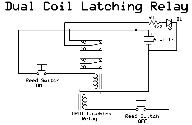
 
If you look at page 43 of **broken link removed** you will see one way to draw the schematic for a DPDT dual coil latching relay.

Les.
 
Gotcha, that's what I was looking for. Anyway, taking into account that mistake, does the schematic exhibit any other problems?
 
schematic_latch_dual_coil.gif
 
I still dont understand that schematic completely. So my DPDT dual coil latching relay has 7 connections. 1 single Pos contact, 2 Neg contacts to control the coil, and 4 contacts for input/output current. I dont see that many contacts in that diagram. How would I depict all my connections?
 
image.png

Yours has the external jumpers on the inside and with coil common = V+ with active low coils, your battery is reversed to this one shown. Thus fewer pins.
 
just the dual pole DPDT relay wiring with 4 contact terminals (2 for motor, 2 for input) and 3 coil terminals , that matches your 7 terminals.
 
Last edited:
Hi dcwatson84,
If you could supply some more information on the latching relay you have it would be helpful. do you have a manufacturer name and part number or the suppliers advert. If bought from ebay then the ebay item number. I suspect your relay is similar to the one Tony has shown in post #146 If your circuit is working reliably there is unlikely to be anything wrong with it. The only remaining problem is for you to be able to draw a schematic that we can understand. If I was building it using a DPDT 2 coil latching relay I would not use the SPST relay. This is the way I would do it.
Schematic01.png


The diode is not really needed. Also if the length of the pulse from the timer is less than the time required for the full travel of the door then the resistor, capacitor and diode would not be needed. (These just generate a short pulse to the latching relay coils.)

Les
 
Here are the two relays:

https://www.digikey.com/product-det...brumfield-relays/RT424F12/RT424F12-ND/1128677
https://www.digikey.com/product-det...tric-works/TX2-LT-12V-TH/255-2854-ND/2125753\

The only reason for the SPST relay is that I dont want the system to consume any power when off. Without the SPST relay there is really no way to do that. The timer pulse can be adjusted to be more or less than the travel of the door, but it's nearly impossible to calibrate it to that exact time . So in my system the timer pulse is short (only ~2 seconds), just enough time for the door to come off the limit switch, at which point the system is in a state where it can run without the timer.

If I draw a schematic of the real components, will that be enough? I.E. labeling my exact components and their contacts? All the other drawings Im seeing seem to be generalized versions of the physical system, whereas I can only understand the physical components Im working with. I don't have any experience drawing the generalized schematics.
 
Last edited:
Neither of the latching relays in you links seem to match up with the information that you have supplied so far. You first showed 6 connections on the latching relay then in the text you say there are 7 connections. The data sheet I found on the web relating to the relay in your first link (RT424F12) show that it has 9 connections. The positive end of both coils is connected to the same pin. The relay in your second link (TX2-LT-12V) is shown as having 10 pins. (Which is what I expect on a 2 coil DPDT latching relay. 2 for each coil, 3 for each of the sets of changeover contacts which adds up to 10.) Do the 2 relays you have match the number of pins indicated on the data sheets I have found ? You can use the way the relays are drawn on the data sheets to draw a schematic.

Les

The link for the DPDT relay was correct, but the other was wrong. Here are the correct ones.

The SPST relay is this:
**broken link removed**
and it has 7 pins.
And the DPDT is this:
https://www.digikey.com/product-det...brumfield-relays/RT424F12/RT424F12-ND/1128677
Which has 9 pins.

What you might be missing is something I mentioned before, the positive contact is common for both coils, so those Relays have 1 pin less than you might expect.
 
Last edited:
Status
Not open for further replies.

Latest threads

New Articles From Microcontroller Tips

Back
Top