Continue to Site

Welcome to our site!

Electro Tech is an online community (with over 170,000 members) who enjoy talking about and building electronic circuits, projects and gadgets. To participate you need to register. Registration is free. Click here to register now.

  • Welcome to our site! Electro Tech is an online community (with over 170,000 members) who enjoy talking about and building electronic circuits, projects and gadgets. To participate you need to register. Registration is free. Click here to register now.

1 sec alternating polarity circuit

Hello all.
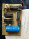
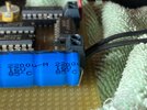
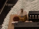
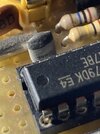
Please see the attached photo of a circuit I’d like to copy. I don’t have the actual board a friend of mine sent me the photo.

It’s a circuit to produce 1 second alternating pulse using the following IC’s-
CD4017B x2, CD4060B x1 and a CD4024B.

Can anyone point me to a circuit diagram for this, maybe there is something online, if there is I’m unable to find it.

I think this circuit is used so it can run on 3v so low power. It’s for pulsing a low voltage Brillie slave clock and needs to be a small footprint so it can go in to the back of the clock and run on batteries.

I look forward to hearing from you.

Regards
Mark
 

Attachments

  • IMG_2209.jpeg
    IMG_2209.jpeg
    1.7 MB · Views: 81
If you have pulse shaping before the output transistors, you would need a full bridge driver with four transistors to so that the pulse could be reversed.
Not if you keep the output capacitor as just an output capacitor. If its value no longer is critical to the output pulse width, its size can be determined only by the load characteristics such as the number and types of clocks. One clock, ten clocks, new replacement clocks, whatever - the pulse widths would be unaffected.

ak
 
Update!
Hi all. This weekend I took delivery of the actual pulsar unit and an 1/2 minute slave clock.
I have the 1/2 minute slave clock now running from the pulsar unit, so I can confirm that it puts out an 30 second alternating polarity pulse.
 
I have a sneaking suspicion this unit gives 1 pulse per 30 seconds - hopefully somebody more adept at working with these chips can confirm (or otherwise) my calculations:

The output of the 4060 (pin 15 , Q10) is 32768Hz ÷ 1024 = 32Hz

4024 output Q6 is ÷ 32 = 1Hz

First 4017 is count of 5 and the second 4017 is count of 6 = 5 x 6 = 30seconds.
Seems like this is correct now I’ve actually tested the circuit
 
The previous schematics should be almost 100%, a meter/continuity check against the actual board would be advised to trace the circuit out and confirm.

Also to confirm the actual transistors/output configuration is right.

Also, what is the value of the big blue capacitor and the little ceramic ones at the crystal please?
Thank you for your reply. I’m out all day today so when I get back I’ll check the values.
 
Just to be crystal (!) clear, the output waveform to the clocks is -

positive pulse > 30 second delay > negative pulse > 30 second delay > repeat

Yes / No

ak
 
Last edited:
Hi. I hope the photos explain a little more.
The axial capacitor is 2200 u-m 16v
The ceramic cap says 8D
The grey/black cap says 39 P

And unfortunately by trying to rotate the axial cap I broke a leg but might be able to dap a bit of solder on to repair it if not I’ll have to replace it (if I can find one).

Hope this helps
 

Attachments

  • IMG_2246.jpeg
    IMG_2246.jpeg
    1.3 MB · Views: 31
  • IMG_2241.jpeg
    IMG_2241.jpeg
    1.6 MB · Views: 30
  • IMG_2243.jpeg
    IMG_2243.jpeg
    814.8 KB · Views: 33
....
The axial capacitor is 2200 u-m 16v
The ceramic cap says 8D
The grey/black cap says 39 P

......
Thankyou, sorry the capacitor lead broke, normally they are little more resilient.

I would suggest putting a bit of hot melt glue of something similar under the blue cap before soldering it back for a bit of extra support - the solder joint will be a weak point now.
 
Does anyone have a reliable source for:

CD4521 - MC14521

CD4536 - MC14536

ak
Digikey carries both for under $1 in single parts (through-hole or SMT) Lower in volume. They are still active parts with samples available from TI.
 
Thankyou, sorry the capacitor lead broke, normally they are little more resilient.

I would suggest putting a bit of hot melt glue of something similar under the blue cap before soldering it back for a bit of extra support - the solder joint will be a weak point now.
Damn it seems like I’ll need a new cap!! The leg broke right at the base but I thought it would re attach with solder, I was wrong Try as I may the solder won’t stick to the base, I’ve tried tinning it, applying flux but no it won’t stick.
I’ll try a locate a new cap.
 
I know there are a few people contributing to this but is there a better method that gives the same results?
Digikey carries both for under $1 in single parts (through-hole or SMT) Lower in volume. They are still active parts with samples available from TI.
Do you have an alternative circuit in mind?
 
Hi all. Can the output be fine tuned with the variable capacitor and is it not better to add one of these in the schematic, what value is the VC in the original circuit?

Many thanks
 
Hi all. Can the output be fine tuned with the variable capacitor and is it not better to add one of these in the schematic, what value is the VC in the original circuit?

Many thanks

Those variable capacitors are generally about 22pF, you should fit it as you need it to adjust the accuracy of the clock.
 

Latest threads

New Articles From Microcontroller Tips

Back
Top