Hello,
I am installing two water float switches - one in each wet well of a basement septic system.
The purpose of these switches is two-fold. First, to activate a horn and give a visual indication of which well has a high water state.
The second is to drive an input coil on a commercial off the shelf relay box that will cut the power to the well pump. This box takes 24VAC (or DC) input and drives a DPST contactor capable of breaking both legs of the 240VAC well pump supply. The circuit simulator didn't have the correct drawing for this relay - so ignore the relay functionality. It is a DPST Normally Closed contactor. When I measure the resistance across the input wires, it reads "open" - so there must be some electronics inside the box that ultimately drive the coil on the contactor.
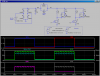
I can create a simple 120VAC circuit which would drive a 120VAC horn and drive a 5:1 transformer to output the 24VAC "signal" for the RIB24.
What I can't figure out is how to put a LED pilot light circuit on each float switch to indicate WHICH float is high. Since they are driving a common source it is giving me fits. I breadboarded a circuit that used diodes to half-wave rectify each branch and put a "polarized" pilot light on each branch, but the transformer didn't like that (got very hot very fast.)
I've got a handful of LEDs, 1N4004 Diodes, .22µF caps (250V), the transformer and some 3K resistors. I could buy a few more components, but am trying to keep the circuit cheap.
I borrowed the pilot light circuit that is illustrated here for the 120VAC side from a web resource (hence the components on hand.)
The floats are SPST "on when up" type switches. They are rated for 120VAC submersed and have 15A contacts (made for direct activation of a sump pump).
Would also prefer to have the entire circuit dead (other than possibly the shown pilot light for the power side) when the switches are down. ie - didn't really want to drive the transformer 24x7.
Any ideas?
**broken link removed**
I am installing two water float switches - one in each wet well of a basement septic system.
The purpose of these switches is two-fold. First, to activate a horn and give a visual indication of which well has a high water state.
The second is to drive an input coil on a commercial off the shelf relay box that will cut the power to the well pump. This box takes 24VAC (or DC) input and drives a DPST contactor capable of breaking both legs of the 240VAC well pump supply. The circuit simulator didn't have the correct drawing for this relay - so ignore the relay functionality. It is a DPST Normally Closed contactor. When I measure the resistance across the input wires, it reads "open" - so there must be some electronics inside the box that ultimately drive the coil on the contactor.
I can create a simple 120VAC circuit which would drive a 120VAC horn and drive a 5:1 transformer to output the 24VAC "signal" for the RIB24.
What I can't figure out is how to put a LED pilot light circuit on each float switch to indicate WHICH float is high. Since they are driving a common source it is giving me fits. I breadboarded a circuit that used diodes to half-wave rectify each branch and put a "polarized" pilot light on each branch, but the transformer didn't like that (got very hot very fast.)
I've got a handful of LEDs, 1N4004 Diodes, .22µF caps (250V), the transformer and some 3K resistors. I could buy a few more components, but am trying to keep the circuit cheap.
I borrowed the pilot light circuit that is illustrated here for the 120VAC side from a web resource (hence the components on hand.)
The floats are SPST "on when up" type switches. They are rated for 120VAC submersed and have 15A contacts (made for direct activation of a sump pump).
Would also prefer to have the entire circuit dead (other than possibly the shown pilot light for the power side) when the switches are down. ie - didn't really want to drive the transformer 24x7.
Any ideas?
**broken link removed**