Continue to Site

Welcome to our site!

Electro Tech is an online community (with over 170,000 members) who enjoy talking about and building electronic circuits, projects and gadgets. To participate you need to register. Registration is free. Click here to register now.

  • Welcome to our site! Electro Tech is an online community (with over 170,000 members) who enjoy talking about and building electronic circuits, projects and gadgets. To participate you need to register. Registration is free. Click here to register now.

220V Basic changeover switch

Status
Not open for further replies.

nishandj

New Member
Hello there,

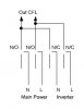
I am thinking of making a basic changeover switch for 220AC. There will be 2 (L - Phase) inputs and one out put line which goes to a 220V-20W CFL Bulb. One input line is coming from the main AC line and other is from some other 220V power base like battery with inverter. When there is power on main line the relay switches it on and if the main line goes down (a power failure) the changeover switch switches on the alternate power source. It will not help to keep the bulb on for 24 hour without any disturbance.

Are there any relay based low cost switches (because I have many lights to switch on)
Or is there a way that diode based switch can be used?

Thanks a lot in advance.

Nishan
 
When you say many lights, do you intend all of them to be controlled by the same changeover switch? Or will they have individual change-over switches? Either way, relays are probably the simplest choice.
 
You don't need a relay even just use a 4pole 230V contactor.

Use 2 pairs for main power in.Use other pair for inverter backup.

But you must select a proper contactor which has both N/O & N/C contacts & it must be 4 pole one.
 
Here is a one I draw within 1 minute.
 

Attachments

  • Inverter Backup.JPG
    Inverter Backup.JPG
    8.4 KB · Views: 459
Can you also please tell me what is the difference between Solid State Relay and Contactor? Thanks a lot in advance.
 
Attached is an image much like the one already posted including the relay coil.

Before Contactor and SSR first let's look at Relays and Contactors. Generally speaking the term Contactor applies more to a high current device. Though the two terms are used interchangeable. For example a device used in a motor starter circuit where a large motor may demand hundreds of amps the term motor starter contactor may be used more often.

A SSR (Solid State Relay) is basically an electronic relay. It is not a mechanical device and has no moving parts. Also, and again generally speaking, a SSR only has what would be normally open contacts. We apply a small low current / voltage control signal to energize the SSR which handles a much larger current or voltage. The SSR is for the most part a Triac or SCR type device. SSRs come in many varieties with their choice for use based on the application.

Keeping it real simple a SSR is a solid state (electronic) switching device while a relay or contactor is a mechanical switching device.

Ron
 

Attachments

  • RY Contact Change Over.gif
    RY Contact Change Over.gif
    8.1 KB · Views: 1,047
Thanks for the info Ron.

So what you say is that when there is power in 220VAC Main the NO is open and NC is closed. But when Main 220VAC is gone, Does the NC gates open automatically? Also the power coming from Alternate Source will not leak to the 220VAC Main? Please pardon me for asking basics but I am not having much knowledge on it and just want to know that when there is power in 220VAC Main, it blocks the Alternate Power and when there is no power in 220VAC Main the NC opens automatically to provide power to the load and It does NOT go back to 220VAC Main. Thanks a lot. And What would be the RY1 COIL?
 
Last edited:
The relay in the drawings has two sets of N/O and N/C contacts. It would be called a DPDT (Double Pole Double Throw) relay. This would be a very common relay. Now the relay has Normally Open and Normally Closed contacts with a Common. With no power applied to the relay coil the common to normally open is just that, it is an open connection and the common to the normally closed is just that, closed. :)

However, when power is applied the relay becomes energized and the normally open becomes closed and the normally closed becomes open. The word "normally" just defines the normal un-engergized state of the relay contacts.

As drawn the load will get power from the mains power source. Look closely at the contacts. With mains power present the relay will be energized. The N/O contacts will be closed to common (the load is on common) and the load powered by mains power. When mains power is lost the relay becomes de-energized (off) and the load is powered by the axillary (emergency) power source. However, when mains power returns the load will be again supplied by mains power. That will happen automatically.

Does that make sense? :)

Ron
 
Status
Not open for further replies.

Latest threads

New Articles From Microcontroller Tips

Back
Top