yngndrw
New Member
Hi everyone,
Well I usually work off of a breadboard or stripboard, but recently some of you may have noticed my post about wanting to start with making my own PCBs.
I've been making lots of PCB designs as practice and I thought I'd make this one - It might be useful to some people here.
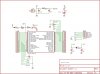
It's designed for 40pin PICs. It *Should* be compatible with the PIC18F452 (Read on about C7 !!) and it is designed for the almighty PIC18F4550.
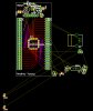
It is designed to go between the PIC and your breadboard in order to perform some of the standard tasks. (Reset, ICSP, Power LED, 20MHz Crystal)
C7 is optional for decoupling the 3.3V output on the PIC18F4550, therefore it is NOT needed on the PIC18F452, but it probably wouldn't cause any harm to leave it there.
It's designed with hand-soldering in mind and is able to be produced on a single sided board with only one jumper. (Although it would be a pain to solder the 2x 20pin headers on the solder side) Also note that there are two components which are designed to sit in the gap of the IC holder, underneath the PIC.
I'm also going to design a SMD version.")
I know there are probably boards which do these functions already, but this one might do things differently ? It's my little thanks for all the help you guys have given me recently.
Anyway, it's all attached in the Eagle format.
Suggestions, improvements, comments ?
Please note that this has not been tested.
Well I usually work off of a breadboard or stripboard, but recently some of you may have noticed my post about wanting to start with making my own PCBs.
I've been making lots of PCB designs as practice and I thought I'd make this one - It might be useful to some people here.
It's designed for 40pin PICs. It *Should* be compatible with the PIC18F452 (Read on about C7 !!) and it is designed for the almighty PIC18F4550.
It is designed to go between the PIC and your breadboard in order to perform some of the standard tasks. (Reset, ICSP, Power LED, 20MHz Crystal)
C7 is optional for decoupling the 3.3V output on the PIC18F4550, therefore it is NOT needed on the PIC18F452, but it probably wouldn't cause any harm to leave it there.
It's designed with hand-soldering in mind and is able to be produced on a single sided board with only one jumper. (Although it would be a pain to solder the 2x 20pin headers on the solder side) Also note that there are two components which are designed to sit in the gap of the IC holder, underneath the PIC.
I'm also going to design a SMD version.
I know there are probably boards which do these functions already, but this one might do things differently ? It's my little thanks for all the help you guys have given me recently.
Anyway, it's all attached in the Eagle format.
Suggestions, improvements, comments ?
Please note that this has not been tested.
Attachments
Last edited: