Continue to Site

Welcome to our site!

Electro Tech is an online community (with over 170,000 members) who enjoy talking about and building electronic circuits, projects and gadgets. To participate you need to register. Registration is free. Click here to register now.

  • Welcome to our site! Electro Tech is an online community (with over 170,000 members) who enjoy talking about and building electronic circuits, projects and gadgets. To participate you need to register. Registration is free. Click here to register now.

555 power-up output state

Status
Not open for further replies.

imix500

Member
Hello all,
Searched but didn't find the answer to this-
I have a 555 used as delay-on for a relay. The output is high for ~5 seconds then goes low triggering a pnp darlington and a large relay. The circuit seems to work great except that once in a while the output is stuck low when power is applied. Cycling power solves it, but is there a simple way to nearly guarantee the output is high on power up?
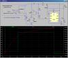
I can post a schematic if needed, but it's just the generic config with Trigger tied to Vcc via 10K and RC of 50K/100uF.
Thanks!
 
Post your schematic. I want to see how you did the trigger.
 
A capacitor connected to the reset pin and ground, a resistor connected to VCC and to the capacitor. This will keep the 555 reset until VCC stabilized. Only a few ms should be required, so make the cap like 1uF or so and the resistor a hundred or so K ohms. Pay close attention to the capacitor polarization.
 
Last edited:
Here's the schematic.
 

Attachments

  • Time Delay.png
    Time Delay.png
    4.7 KB · Views: 790
Why is R4 where it is????
It should be tied to +12V; not to ground. Your output Darlington is partially always on????
 
Last edited:
Why do you need the Darlington?

From memory, the 555 can source & sink 200 mA, so that should be more than enough to operate the relay.

Don't neglect to connect a diode across the relay coil to limit the back emf to a safe level.
 
So, the timing cycle is supposed to be initiated when 12V is applied to the circuit?
 
I rarely use the 555, it is usually simpler to use a CMOS Schmitt Trigger.

Here is one I designed for someone else.

It could be adapted to your purpose.
 

Attachments

  • Delay 1 s.gif
    Delay 1 s.gif
    42.5 KB · Views: 262
Last edited:
ljcox,
I don't think I have any Schmitt triggers, but I can look tomorrow.
I do have 4541 timers if they would be a better choice.
 
The 4541 would need a "power on" reset.

The crude way to do it would be to connect a resistor from MR to Gnd and a capacitor from MR to Vcc.

The better way would be to use a 555 or a Schmitt Trigger.

So it would be much simpler to use the circuit I attached previously.
 
This should do it: Leave the Discharge pin open. Hook TRIG to THRESH. Use diode to discharge timing network when power is removed.

Your circuit didn't have a reliable trigger mechanism.
 

Attachments

  • DF65a.png
    DF65a.png
    41.8 KB · Views: 313
Last edited:
So I built the circuit MikeMi posted this morning and it has been running for over 100 power cycles without missing a beat. Unless something happens with it in the next few hours I think the problem is solved.
Thanks for the help!
 
Status
Not open for further replies.

Latest threads

New Articles From Microcontroller Tips

Back
Top