HI,
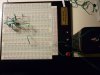
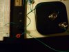
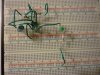
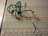
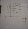
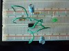
I tried routing my circuit different ways, but I can't get the LED to come on.
Could someone please enlighten me as to what I am doing wrong?
Thank you!
I tried routing my circuit different ways, but I can't get the LED to come on.
Could someone please enlighten me as to what I am doing wrong?
Thank you!