Continue to Site

Welcome to our site!

Electro Tech is an online community (with over 170,000 members) who enjoy talking about and building electronic circuits, projects and gadgets. To participate you need to register. Registration is free. Click here to register now.

  • Welcome to our site! Electro Tech is an online community (with over 170,000 members) who enjoy talking about and building electronic circuits, projects and gadgets. To participate you need to register. Registration is free. Click here to register now.

AD558 output boost

Status
Not open for further replies.

Sceadwian

Banned
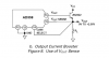
I picked up a couple DAC chips earlier today at a surplus store in town that had them for like 4 bucks cheaper than digikey. I was browsing the PDF and noticed since the feedback to the internal buffer amp is available on one of the pins you can use a current boost transistor to increase output current, they use the venerable 2n2222 as an example and I do have a few around if I want to use one, but I was wondering if I could just substitute say one of the 4 amp mosfets I have instead to use it as basically a digital variable linear voltage regulator. Bellow is a capture of the part of the PDF that shows the boost setup and a link to the full PDF. It doesn't contain much information aside from the simple example.
https://www.analog.com/UploadedFiles/Data_Sheets/AD558.pdf#xml=https://search.analog.com/search/pdfPainter.aspx?url=http://www.analog.com/UploadedFiles/Data_Sheets/AD558.pdf&fterm=ad558jn&fterm=ad558jn&la=en
 

Attachments

  • AD558-boost.png
    AD558-boost.png
    13.3 KB · Views: 268
I would expect the AD558 to be able to overcome the threshold voltage of a logic driven MOSFET, if Vcc is high enough. I wouldn't expect an ordinary MOSFET to work quite as well.
 
The only power FET's I have are IRF510's. I'm concerned about oscilation problems since a FET's active regioin (especially a logic fet) is so small, and non linear.
 
It doesn't matter, I've used power MOSFETs in their non-linear region before without any problems but you need to ensure the gate is sufficiently above the source or the voltage drop will be enourmous.
 

Attachments

  • Ultra low dropout.GIF
    Ultra low dropout.GIF
    5.3 KB · Views: 278
The DAC is 10 volts out, should be plenty.
 
But if you're using a source follower, then the maximum output will be about 5V depending on what current you're drawing. This is why you need a voltage doubler and op-amp to to shift the voltage up above the supply to get a decient dropout voltage.
 
I thought the opamp on the DAC is what did the voltage following, simply connecting the sense/gain pins to the point where you want the voltage to follow and the VOUT should go from any voltage from 0-VCC in order to get the sense voltage to coincide with the DAC's currently set value?
 
I don't think you understand what I'm saying, I might not be explaining it very well.

With an emitter follower you loose 0.6V + the saturation losses, with a MOSFET you loose the threshold voltage + the conduction losses. Since the threshold voltage on a MOSFET is so high you'll need to power your circuit from >15V to get 10V at any reasonable current. To get round this you use a smaller power supply for the gate driver circuitry.
 
Never mind Hero, sorry I wrote that post in a hurry I realized what was wrong with it right after I left =)
 
Status
Not open for further replies.

Latest threads

New Articles From Microcontroller Tips

Back
Top