Continue to Site

Welcome to our site!

Electro Tech is an online community (with over 170,000 members) who enjoy talking about and building electronic circuits, projects and gadgets. To participate you need to register. Registration is free. Click here to register now.

  • Welcome to our site! Electro Tech is an online community (with over 170,000 members) who enjoy talking about and building electronic circuits, projects and gadgets. To participate you need to register. Registration is free. Click here to register now.

alternative way of charging 330V caps?

Status
Not open for further replies.
You're most welcome :D

I could have made several posts about different methods, from making a charger completely from scratch (wiring own transformers, or designing boost converters etc..) or using off the shelf easy to find 'modules' such as camera flash units. Looking at the schem provided by harvey, building that from scratch wouldn't be too difficult even for an amateur, except...the transformer. Making/buying these is tough. They are small, not jstu because of the low current they work at but also the frequency, they really are specifically designed for this app.

Believe it or not I have made my own little transformers for a high powered 12V strobe. Its a ***** to say the least. So I shall abandon any advice about making a charger from scratch.

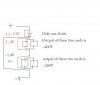
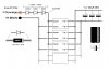
Of course you could desolder the transformers from your camera flash boards!! but I don't see the point really...as the flash boards will already have everything else you need on them. Heres a quick diagram of the hookup I would use to start with. First things first, get it working reliably (no failures/burnouts/pretty sparks) then mod for lower charge times.

As for 'charged' indication, I would have thought the neon lamps on the flash boards would light up more or less at the same time.

Blueteeth
 

Attachments

  • capcharge1.jpg
    capcharge1.jpg
    69.6 KB · Views: 162
Last edited:
Well my first thought was a simple audio transformer for T1, but it seemed like a lot to expect from the little thing.

Back in the day, Pukefest M Mimms III used a 8:1000 ohm audio transformer to run a neon light flasher. While that circuit would work to charge the capacitors, I have no clue how long it would take to charge over 1200uF with that thing.

Dan
 
Well my first thought was a simple audio transformer for T1, but it seemed like a lot to expect from the little thing.

Back in the day, Pukefest M Mimms III used a 8:1000 ohm audio transformer to run a neon light flasher. While that circuit would work to charge the capacitors, I have no clue how long it would take to charge over 1200uF with that thing.

Probably longer than the flash units :D

I think he needs to look at this in a different way, he's using mains power and transforming it down to a low voltage to feed small battery flash units. Why not just use a simple AC transformer from the mains to INCREASE the mains voltage, rectify it, and charge the capacitors directly.

This is how commercial studio flash units work, giving much higher power, and far faster charging times (as fast as the camera can cycle).

It also how strobes work, which flash far, far faster than camera flashes.
Beats me, only thing I can think of is a misplaced sense of safety. There is a reason that the medical safety specs call out high isolation to the patient from both high voltage AND high power circuits .
 
Well, even though the OP is charging high voltage caps, at a voltage that can be lethal, some don't like to deal with mains directly. There is good reason for this, I have been zapped a few times and it isn't nice, so you can understand why many choose the convoluted route of stepping down mains, then stepping it up again. At least then the only 'danger' points are either inside a propritary power supply, or at the charging caps themselves.

Also, the mains transformers mentioned aren't easy to find for the amateur. Sure, mains -> 12v is easy to find, but a 1:1 ratio? or even a step up? Only ones I've seen are those designed for valve equipment.

lets keep this simple people. The op isn't after efficiency or elegance, just something that will work, the he can learn from and won't kill him if he puts his screw driver in the wrong place.

Blueteeth
 
Uhhh i have a weird problem.

i hooked up the schoktty diode in series with 2 other flash cards.

During testing, the voltage drop across the diode was about 0.3..

after hooking it up, the voltage drop became 2 VOLTS???

Now my flash cards are putting out separate voltages, one at 450 volts, the other at 200ish volts.

my question: WTF?
 
What is the part number of thes shottky diodes? The voltage drop across a diode increases as the current through it increases. I find it hard to believe your 'flash cards' (I'm assuming you mean camera flash charing boards) will draw more than 300mA each, there for 2 flash cards in parallel, thats 600mA. Your diodes sohuld be rated at at LEAST 1amp (1000mA). These are usually the same size as standard power diodes, like the 1n4001's, black, and rather large.

If you're getting a drop of 2V acorss two diodes, thats 1v drop, thats pretty much the absolute maximum drop a diode can do, and is usually when its at its maximum rated current. It will disapate (absorb) 1V * current. they usually get really hot at above 0.5W so anything more than 500mA, you're risking them popping. Which could blow your whole circuits, as diodes tend to 'short' when they go.

Please draw a diagram of your setup. If doesn't have to be detailed, the 'flash cards' can simply be boxes, but jstu to show where the diodes are.

Also note, if you measure the voltage of the output of a charger with no capacitor connected, they will be 400V+. They were never designed not to have a load on the output, and are completely unregulated. Remmember, when charging capacitors, its voltage increases over time, so the 'flash cards' deetect when the cap is charged by checking the voltage across the capacitor. When its roughly at 300-330V, a neon light, lights up.

Sounds like the large difference between the outputs is, either one 'flash card' has blown/faulty because it got two much voltage, or if you hooked it up without a capacitor to charge on the output, then it may have shorted, which again would brlow some components.

I know my previous posts were long but if it helps, re-read them. I'm still unsure if the cameras you got the 'flash cards' are from were designed to run off one AA battery, or two. (1.5V, 3V). If you try to run a 1.5V flash card from 3v, its relaly not going to like it, as it would draw much more current, putting a strain on the components. And its output, measured with no cap connected would be waaaay above 400V.

Blueteeth
 
Last edited:
This circuit is acting Sooo weird. I took the cards i had before, and obtained two other ones that are different. These different cards are causing weird effects i think. when the circuit is first turned on, the Neon lamps are off or barely flashing...

At this point i measured the following:
So voltage drop across diode is ~1.8 V.
total across entire circuit, EXCLUDING diode is ~1.5
voltage drop across one bank of flash cards is oddly... 0.7 volts.
Voltage drop across other bank of flashcards is.... 0.6 volts.

Outputs:
Flashbank 1: Input 0.7V, output ~300V?
Flashbank 2: Input 0.6V, output barely 210 V?


...
Eventually the Neon Lights will turn on. When i measure the voltage now, everything is different.

Diode:~1.6V
Flash card bank inputs: ~1.1v 0.8v
Flash card bank outputs: 330V, 160V

There are also mixed results. Sometimes the lights are not very bright, sometimes they're at full brightness: I was only able to get some readings before the lights got dimmer:
Outputs: Barely 210V and 430V.

I dont know the code for the schottky diodes that i got. I bought two, but one of them broke (like the glass just shattered.)

...
The power supply puts out constant 3.3V.


untitled-jpg.24352
 

Attachments

  • untitled.JPG
    untitled.JPG
    18.7 KB · Views: 269
Last edited:
Saibot,

Thanks for the diagram and measurements. It makes it a hell of a lot easier for me, or others to debug your circuit without having to go there and actually poke it with our own multimeters like geeks in heat :)

Heres my thoughts on whats going on.

Firstly:
I dont know the code for the schottky diodes that i got. I bought two, but one of them broke (like the glass just shattered.)

Glass diodes are almost always designed for signals, not power. Therefore their rated current is much lower, usually about 200mA maximum. Now, I'm pretty sure that a single charger circuit would take about 200mA, maybe more. In the configuration you have (2 parallel groups of boards, in series) then because you have two paralleled, combined they take 400mA. This, if not enough to blow your shottky diode is most certainly giving it greif, thus its ridiculous voltage drop :D

Alternatives are: 1) Get some power shotky diodes, rated at 1A+ such as the 1N5817, 1N5819. OR 2) Use Standard power diodes, non shottky, just plain old silicon power ones. Aka the 1N400X (X = 1 to 7). The only reason shittky's were suggested in the first place was because we assumed (wrongly) that you wanted 3v from a 3.3v supply. And shotkys have a smaller voltage drop.

Secondly:

The confugration you've used, using both paralle and series configurations, in an ideal world should be fine. If all went to plan, they would each have 1.5 across them, and drawing the same current. In the practical world things rarely operate that way.

For a start, these circuits will not 'drop' a certain voltage. That depends purely on how much current they get, so you must regulate either one or the other and its FAR easier to regulate their voltage, and let them draw whatever current they need. Also, the problem with series configurations is...the output of each is referenced to 0V. That means that usually (may not be) the negative of the output (going to the - of the cap) is connected to the GND of the input. In series you have two 'GND's, which are at different voltages. This means that current can flow from one circuit to the other, when you connected them up. The ONLY exception to this is if you are using each 'paralleled' group to charge a seperate cap bank. If you are charging one big bank, then you can't have them in series.

So, sorry to tear up your circuit but here's what I would do :D

Put all boards in parallel. So that means all the negative inputs (GND, 0v) are connected. Do the same with the power input. I understand you want them to have 1.5V across them, and you have a 3.3v supply, but you will have to use diodes to drop this, as putting boards in series, at least for YOUR purpose, isn't wise.

Refer to the diagram I provided in a previous response. In that simple configuration, each board gets the same input voltage (1.2V to 1.5V) but will draw its own current. If they are all the same type them they should all draw the same current. Also use standard pwoer diodes, a LOT easier to get hold of. Perpas its not that efficient, but its safe, and should be reliable. So at least its a start so you can get things working. You could change the circuit to convert 3.3V to 1.5V later on. First, get things working without blowing stuff up :) (took me years to learn that)

If you don't connect the outputs together, you can measure every individual boards output. Should be more or less the same, but without a capacitor connected, its pretty muich meaningless, as the CAP determines the output voltage. It will rise as the cap charges, then level off at around 300-320V. Unconnected could be up to 400V+. You can now connect up all the outputs in parallel. NOT series. In parallel everything has the same voltage, but is capable of providing more current. In series, everythign gets the same current but has different voltage drops.

Now, to explain why you measured the voltages you did:
These units are designed to operate from a single AA cell. When you draw a lot of current form a cell, their voltage drops. So even a new AA battery, when powering sometihng that takes 200mA, its voltage will drop to about 1.3V. Also, as the battery wears down, its voltage drops, so anything designed to be powered by them usually can operate down to 1.0-1.1V. So the units that had 0.9V across them, were in fact working quite well (400v output). Where as the units that had 0.6V across them weren't, because thats below the voltage of a 'dead AA battery'.

As I keep saying when you measure the output of these boards, without anything connected to them, you'll measure huge voltages. This is because, as you draw more current from them, their voltage drops. Without anything to draw current (multimeters don't really draw anything) theirs nothing to hold the voltage down so it could reach 500V.
When you connect a capacitor across it, its voltage will drop, and, as the cap starts to charge, it'll rise slowly, settling at a voltage UNDER the 330v which the caps are rated at. So, don't worry about 400V, it won't ever get there when charging your capacitors...providing you don't give the units more than 1.5V each.

Sorry for the long post. I hope that explains all.

Blueteeth
 
Last edited:
Status
Not open for further replies.

Latest threads

New Articles From Microcontroller Tips

Back
Top