Continue to Site

Welcome to our site!

Electro Tech is an online community (with over 170,000 members) who enjoy talking about and building electronic circuits, projects and gadgets. To participate you need to register. Registration is free. Click here to register now.

  • Welcome to our site! Electro Tech is an online community (with over 170,000 members) who enjoy talking about and building electronic circuits, projects and gadgets. To participate you need to register. Registration is free. Click here to register now.

Anyone had luck with these MPPT boards? It blew up on me.

Status
Not open for further replies.

nzoomed

Member
Im needing to charge a 6S lithium battery bank comprised of 12 x 21700 lithium cells from a 50W panel.
Panel voltage is about 18V or 22V open circuit.
I had one of these MPPT boards floating around ( https://www.aliexpress.com/item/4000552321010.html ) and when I went to set it up using my benchtop power supply starting with about 8V, I tried to adjust the output voltage but couldnt get much more than 15V out of it no matter how much I tweaked the pots.
Increasing the benchtop power supply voltage would help, but I could not get much close to the battery voltage without cranking up the supply voltage of the power supply to that which exceeded the solar panel voltage.
Anyway, I thought I might have had to have added a load while testing, so connected the battery pack and I think it killed the board. I could smell a burnt smell but no smoke.
Specs say 26V is the maximum output voltage, so this should have worked I thought, even though my battery voltage is about 25V

I dont know if i did something wrong, the poorly translated instructions seem vague, but from what I could make out if it, you adjust the MPPT pot until the LED starts to flicker, and adjust the other pot to suit your output voltage.
Is that right?
Either way, I need to find a charge controller that can charge this bank.
TIA
 
OK, I will take a look at that.
What about the controller you quoted in post no4?
As I have already got a 15watt panel, this might be the best approach for now, but I was hoping there is something I can quickly put together myself with off the shelf parts that can get me going while I wait for something to arrive out of China.
 
What about the controller you quoted in post no4?
That may work OK; it would be running at it's limit though, and from experience a lot of those little power modules have exaggerated ratings so I'd not count on it's reliability at 2A.

The Amazon MPPT units are not much different in cost & have vastly better ratings, plus good customer feedback - I did not know they were so cheap when I was looking for Aliexpress modules!
Those units on Amazon appear to be PWM not MPPT.
They might do the job but won't be as efficient.
Also looking at this schematic, not sure if it will function any better than what I got, but its easy enough to build.

 
Last edited:
Those operate by taking all the solar panel current, to cap the panel voltage at a suitable level.
They do exactly what you were trying to do with the little boost converter, but with much better ratings than those.

The true MPPT versions cost slightly more -


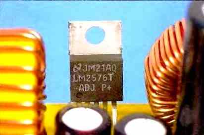
Re. the LM2576

Those are the basis of many of the cheap buck converter modules:


They are again not charge controllers.
 
MPPT does not imply boost, only that the load on the solar panels will be adjusted for optimum output.
The input voltage to output voltage range is a separate feature, depending on the system.

You could run one of those MPPT modules in to a fixed boost converter, to get the voltage you need without having a higher voltage solar panel setup?

ps. Be wary of "BMS" modules - they are not charge controllers, only voltage protection and [hopefully] cell balance.

Conventional lithium cells need a charge controller with current and voltage control, plus a total cut-off at full charge if using the cells to full capacity.


One of these may be suitable? 2A out at around 24V, so close to 50W:

It does still need a BMS with balance circuit, to protect the cells in the battery pack.
So i ordered one of these and it seems to be working.
I initially tested on my benchtop PSU to simulate the solar panel power and it was only drawing about 1.2 amps and not putting anywhere near its 2A output into the batteries.
That being said, it didnt seem to be taking too long to charge the battery bank from near empty, after a couple of hours last afternoom with the sun on its way down and the battery voltage was up to almost 24V.
Today its a cloudy day and the panel is only providing about 300mA, but its still charging, If its charged by the end of the day I will be happy, but I am yet to add the load with the camera to put it really to the test.
I question whether this panel is capable of providing its rated current, but will have to monitor on a real sunny day.
 
Would this be any better?
I question whether its efficient or just not designed to provide the 2A of current as advertised, even with my lab power supply, i was only getting 1.2A out of it
I also question whether the solar panel could provide as much power as advertised, but need to try different controllers.
The battery pack charged up to just over 24V, so 4V per cell, not 4.2V.
On a cloudy day today I was only getting about half an amp at times, and only charged up to about 23.1V
 
That does not have any kind of charge cutoff for lithium cells, only constant voltage and current limit.
It is again voltage step down only; it does not even have any protection from the battery feeding back when there is insufficient solar input.

I'd not trust it; it does not even appear to be a true MPPT device, as the instructions say to manually adjust the input voltage to the max power point...
Ok, I will stay clear of it.
The unit I've got is working at least, but would like to find something better eventually.
Not only is it not using the maximum power available from the panel, but it doesn't charge the batteries 100% which is not necessary a bad thing for extending cell life, but maximum capacity would be ideal.
I'm wondering how easy it would be to design my own custom unit?
Adding on that earlier open source design to accommodate 6 cells would be an attractive option.
 
Sorry to be a pain, but ive been searching through a few listings.
This unit looks a bit more suitable. I would only need the 4A version.
Any thoughts?
Also would like a better BMS recommendation .
Im currently using this.
I see a multitude of different BMS boards, some say they are active and have better features, i suspect that it is just a protection board to prevent discharge/overcharge?
 
That appears to have all the same problems as the previous one..

These are true MPPT controllers, from the description?


For BMS modules, I prefer ones that have clearly visible, large, balance resistors. Balance is essential in any series lithium cell pack, and larger packs need higher balance current.

eg. like this - you can see the line of big resistors next to the connector:

I can't find anything like that for six cells on Aliexpress.

Also, it should be protection and balance in the same module (at least for passive balance) - with random combinations of protection and balance modules, the voltages may not match and the balance never start working, or be unreliable.

I've not tried an active balance one yet; they should transfer energy between cells, rather than just loading the highest voltage cells.
OK, I couldnt find any way to tell if it was a buck or boost module, but it looked closer to the type you mentioned in post #4 with the exception of being adjustable.
That unit you suggested in that post is working but Im not getting as much current as I would have liked to have got from it.
Those larger units like you linked to are probably a better option as you say, but are a but bulky and I was hoping to not require too larger an enclosure to put everything inside. If I could just find another board, that would be ideal.
That BMS board does indeed look better quality and I get the feeling the one ive got is just a protection unit rather than a balancer, so I will order some.
 
That appears to have all the same problems as the previous one..

These are true MPPT controllers, from the description?


For BMS modules, I prefer ones that have clearly visible, large, balance resistors. Balance is essential in any series lithium cell pack, and larger packs need higher balance current.

eg. like this - you can see the line of big resistors next to the connector:

I can't find anything like that for six cells on Aliexpress.

Also, it should be protection and balance in the same module (at least for passive balance) - with random combinations of protection and balance modules, the voltages may not match and the balance never start working, or be unreliable.

I've not tried an active balance one yet; they should transfer energy between cells, rather than just loading the highest voltage cells.
rjenkinsgb
Ive been looking at the datasheet for this IC and it appears it should be up to the job, Im looking at the schematic in the datasheet and it appears the board layout is loosely based on the datasheet schematic.
Is there any component value I should check that could be limiting the output current?
The resistor value for Rcs appears to be for current sensing, this board appears to have a 60 ohm resistor, would changing this resistor increase or decrease the output current? I want to get the maximum current available and testing on my lab power supply shows that even in a situation where input current is plentiful, its only putting in about 1.2A. If i could get closer to the 2A thats advertised, that would be great.
If its just a simple swap out for a different resistor to change this, then that would be awesome.
 
In the diagram Rcs and Rsw are the current sensing resistors, for battery charge current limit and overall power limit. I'd expect both of those to be a fraction of an ohm?

60 Ohms in either position would limit current to small fractions of an amp.
 
In the diagram Rcs and Rsw are the current sensing resistors, for battery charge current limit and overall power limit. I'd expect both of those to be a fraction of an ohm?

60 Ohms in either position would limit current to small fractions of an amp.
Your right, its pretty low, my meter cant be that sensitive but its reading zero ohms.
Its stamped 060, i assumed that meant 60 ohms, but its not even reading as 0.6 the meter leads measure 0.3 ohms, and thats all I get when measuring it.
I see that pin 1 is supposed to connect to the battery for feedback voltage input, but its not connected on this unit, but I dont think its required for MPPT use?
0060 could well be 0.060 ohms (60 milliohms).

I commonly use 0.1 ohm for current sensing, which is less than double 60 milliohms.

I'd certainly suspect that 60 milliohms is the most likely value - basically you want it low enough not to waste much energy, and for the same reason not to dissipate much energy (to avoid needing a large resistor that runs hot). On the other hand, you want it high enough to drop enough voltage for your measuring system, which will usually include an opamp to amplify the voltage drop.

For an example:

For 2amps a 0.6 ohm will dissipate 2.4W, a 0.06 ohm will only dissipate 0.24W
OK, any reason that the charge current is so low then? Anything else I should look at?
Im getting up to 1.3A into the battery and its only drawing 1.7A from my power supply.
This IC is designed to handle up to 5 amps, but I only need 2 amps, If its possible to tweak this to get more power, it would be beneficial.
But that being said, I dont know how easy it would be to develop something better, ive also ran into a problem where I am planning to run PoE over this unit which requires 48V, but less than half an amp of current.
Ideally using a boost converter is inefficient, but is easier to step voltages down than up.
I could reconfigure the bank to 12s and use a step down converter from 50V, but finding a 12s charger is proving difficult, so will probably go with a boost converter for the time being.
Do any MPPT IC's here look suitable?
Looks like development boards are available.
 
Last edited:
Status
Not open for further replies.

New Articles From Microcontroller Tips

Back
Top