Electro Tech is an online community (with over 170,000 members) who enjoy talking about and building electronic circuits, projects and gadgets. To participate you need to register. Registration is free. Click here to register now.
Welcome to our site! Electro Tech is an online community (with over 170,000 members) who enjoy talking about and building electronic circuits, projects and gadgets. To participate you need to register. Registration is free. Click here to register now.
The inverting type is a waste of the Fet-input opamp. The gain depends on the source's impedance. The input impedance is low so the input coupling capacitor cuts frequencies below 133hz and even 665Hz is dropping a little.
If the circuit is made as a non-inverting type then it will have a high input impedance and good bass response. Its gain will not be affected by the source impedance.
You did not make a mic preamp since you didn't use a mic. You made a line-level preamp that was driven from an MP3 player. Its small-value input capacitor (or its low input impedance) reduced its bass response.
No.
Your circuit is NOT non-inverting. It is inverting with a low input impedance.
The input impedance is only 12k ohms which is too low for an electret mic but is fine for a low impedance dynamic mic.
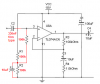
Your new preamp circuit uses an opamp with an extremely high input impedance.
But the two 47k input biasing resistors create an input resistance of only 23.5k ohms then the input capacitor needs to be a lousy distorting electrolytic type with a fairly high value.
A volume control at the output of a preamp reduces hiss when it is turned down. But the preamp is overloaded when a high input signal happens which causes severe distortion.
With the volume control at the input of the preamp then it can be adjusted so that high signals do not cause severe distortion but it still has hiss when it is turned down.
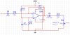
The preamp circuit will drive a load of 2k ohms or more. But since the TL074 has very high frequency response, it oscillates if it directly drives the capacitance of a shielded audio cable. A 100 ohm resistor in series with its output will isolate the capacitance of the cable from the opamp so it does not oscillate.
The control should be at the output of the preamp (often you would have a switched attenuator at the front as well), and you should sum them using a virtual earth mixer - and you would have had no trouble.
Feeding the output of this preamp into the inputs of 3 other preamps?
Or feeding the outputs of 3 mixers into one input of a power amplifier without a mixer?
Regarding my non-inverting design, are the values of my capacitor correct? I tried the design and used a dynamic microphone as an input. The output is a fair enough but there's a hum.. how could i get rid of the hum?
Your mic preamp had R1 feeding hum from the power supply into the input of the preamp.
I added another resistor so that R1 and R2 have an added filter capacitor.
I also used a lower value non-polarized input capacitor.
Of course the circuit should be built on a small pcb or stripboard since the many long wires of a breadboard are antenna to pickup mains hum. The cable from the mic to the input of the circuit must be a shielded audio cable which is called a screened cable in the UK.
You could utilize the other 3 op-amps in the TL074 package to increase the gain in stages, to get a better dynamic range,reduced noise & enough signal to drive an power amp IMHO.since a gain of more than 8 in the buffer /1st stage will make the circuit unstable & render it prone to both feedback & excessive noise.
Importantly,both Back-electret & condenser mics have considerably high impedance,hence these must be run on a non inverting buffer pre-amp. On the other hand,dynamic mics have relatively low impedance under 1000ohm & therefore can be easily driven by pre-amps with inverting input buffers.
The only snag is that, in order to drive electret & condenser mics,these require a DC (bias) voltage anything between 2v to 48v DC! This not at all difficult & can be tapped from the battery or the power supply to the circuit with a few components.
This site uses cookies to help personalise content, tailor your experience and to keep you logged in if you register.
By continuing to use this site, you are consenting to our use of cookies.