Kingpin094
New Member
I will start this off by saying that I am not an audiophile, so be nice. I am not a noob to electronics
just to making audio base circuits.
This is on of those projects that came up out of the pile of stuff and a general desire to take a
break from the other 12 projects that are currently going on. It started off by wanting to add some
tunes out in the garge to replace the little crapy FM radio that came with a Black and Decker cordless drill.
I had a pile of bose computer speaker systems that looked like I would be able to plug into the garage
computer (I know, I know electronics dork...) but they run on SPDIF. Since the computer doesn't have
digital outs I thought "Hey I am an electrical engineer I can just bypass the input and go stright to the amp!!".
Novel idea and given enough boards I could probally get it right but only had two tries and used them both up") .
.
So know I have speakers and no amp.... hmm. Lets check the parts box to see what I can find. Low and
behold I have some LM4755's and LM1875's from a previously abandoned project.
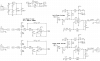
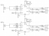
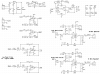
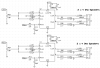
Attached is the preliminay circuit digram for the 6 speaker system. The input will be from a coumpter sound card.
Assuming that voltage is ~1Vpp? Not sure crappy oscilloscope doesn't do really will with random signals.
Anyway I had some questions and I know there are some audio guys out there so here we go:
1) In the circuit I was going to put each channel of the input to 3 different outputs. A front, back and
sub for left and right. In order to get the input to go in all 3 places to I need to buffer input?
2) Is there going to be a problem in tying both inputs to the LM4755s together but still having seperate outputs?
Before I go off and start building does anyone see anything that might be an issue?
Thanks to all who reply,
kingpin094
just to making audio base circuits.
This is on of those projects that came up out of the pile of stuff and a general desire to take a
break from the other 12 projects that are currently going on. It started off by wanting to add some
tunes out in the garge to replace the little crapy FM radio that came with a Black and Decker cordless drill.
I had a pile of bose computer speaker systems that looked like I would be able to plug into the garage
computer (I know, I know electronics dork...) but they run on SPDIF. Since the computer doesn't have
digital outs I thought "Hey I am an electrical engineer I can just bypass the input and go stright to the amp!!".
Novel idea and given enough boards I could probally get it right but only had two tries and used them both up
.So know I have speakers and no amp.... hmm. Lets check the parts box to see what I can find. Low and
behold I have some LM4755's and LM1875's from a previously abandoned project.
Attached is the preliminay circuit digram for the 6 speaker system. The input will be from a coumpter sound card.
Assuming that voltage is ~1Vpp? Not sure crappy oscilloscope doesn't do really will with random signals.
Anyway I had some questions and I know there are some audio guys out there so here we go:
1) In the circuit I was going to put each channel of the input to 3 different outputs. A front, back and
sub for left and right. In order to get the input to go in all 3 places to I need to buffer input?
2) Is there going to be a problem in tying both inputs to the LM4755s together but still having seperate outputs?
Before I go off and start building does anyone see anything that might be an issue?
Thanks to all who reply,
kingpin094