Continue to Site

Welcome to our site!

Electro Tech is an online community (with over 170,000 members) who enjoy talking about and building electronic circuits, projects and gadgets. To participate you need to register. Registration is free. Click here to register now.

  • Welcome to our site! Electro Tech is an online community (with over 170,000 members) who enjoy talking about and building electronic circuits, projects and gadgets. To participate you need to register. Registration is free. Click here to register now.

battery spot welder problem

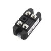
I got a cheap spot welding board and wanted to test it out. Since i got no LiPo handy, i thought i could use a microwave transformer and a 100A 1600V rectifier since board needs DC. I tried with both 7.5V and 12V coming out of the transformer. I basicaly get nothing. It barely shows on the 0.1mm strip, doesn't go through. If i had to guess i would say im not even getting 1 amp out. Transformer should be more than capable to supply enough amps to at least make a spark. Is there something im missing here ?
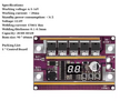
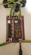
20250413_010002.mp4_snapshot_00.02.487.jpgScreenshot 2025-04-13 020407.pngS35101595a88a4716b093c6bc5f58bfe52.jpg
 
I don't see any smoothing capacitors. If there are no smoothing capacitors after the bridge rectifier, the power going into the board is pulsating AC, not DC.
I used a capacitor bridging the terminals on the input to the board. The problem is that all i have are small capacity caps and the ripple equation is giving me numbers in mF
 
If you can't put a lot of low ESR capacitors in parallel to make a capacitor bank then a car battery may work if you can't get a LiPo.

Also, I suspect that the spot welder may work to some extent if you can get a stable DC voltage to the control electronics even if your high current supply is poorly regulated. The issue with a poorly regulated supply driving both the control electronics and the high current output is that if whenever you try to weld the voltage drops then the control electronics will also stop working. I see two DC inputs on the board. Are these tied together internally?
Sadly, they are. It's just 2 different inputs so you can use cables like i do, or plug in the lipo directly if you add the female plug.

I have a bunch of 18650 20A cells. I wouldn't use them for the spot weld cause its inpractical compared to lipo (would need many many cells). But a 2S5P bank should at least be enough to test the board and see if i get a spark, right ?

edit: i have misread the equation. It would appear that in my case, a 20.000-50.000uF should be enough to smooth the ripple. I will give it a go, connect 10-20 caps in parallel and see if it makes a difference
 
Last edited:
Capacitors are the safer option so I'd definitely try that before the 18650s.

Connecting 18650s in parallel may work. The 20A rating is for continuous discharge, right? If so, the pulse current rating will be higher and you may be able to get several hundred amps for a brief pulse. If you only run the welder intermittently the 18650s should not get hot enough to trigger the built-in protection devices. The cells will have a max pulsed current rating though and I'm not sure what exceeding that will do, so proceed with extreme caution if you are not sure that you are within the limits on the datasheet.

Edit: you may want to initially test the welder outside if you're using 18650s just in case
 
I tried the setup today by adding 23500 uF cap bank (35V handling). Input into spot welder was about 7.5V. I was certanly able to make a dent in the thin battery tabs now, not enough to spot weld to batteries though.

So now i am still stuck between either rectifier is blocking to much current or the board is not working right. Rectifier i can test by just shorting it through a 0.2mm tab and see if it makes a hole, but for the board, i will have to find someone with a proven lipo or car battery.

I really didnt think i would have a problem with to little juice when using a transformer. Rather i thought i would spend lots of time fine tuning it to prevent holes in batteries. And i find it mind bogling that a phone size lipo in that pocket spot welder puts out a lot more juice
 
A 23.5mF capacitor bank charged to 7.5v will discharge to 0v in less than a millisecond (587.5uS) assuming a constant current draw of 300A (I = C * dv/dt). Since you're discharging through a resistive load (not constant current), the time will be slightly larger and dictated by the time constant formula. The issue is that at 7.5v the caps will almost immediately go below 6.5v which is the minimum working voltage of the board according to your image. This means that you will not be using the full energy of the caps because the board will stop working almost immediately when the voltage drops. If you can, try charging them up to ~15v since they are rated for 35v. You may get better results with that.
 
In the meanwhile i did some more testing and it would appear that rectifier certanly holds part of the blame. I tried shorting the outputs over 0.2mm battery tab and it barely left a mark. If i did this with transformer output, the tab would instantly vaporise.

I also did current testing and shorting the outputs, i get 10 amps. So, i dont know if the problem is that it's a cheap chinese rectifier, or that its rated for 1600V 100A and basicaly 10 amps is all i can get out at such low voltage.
 
I also did current testing and shorting the outputs, i get 10 amps. So, i dont know if the problem is that it's a cheap chinese rectifier, or that its rated for 1600V 100A and basicaly 10 amps is all i can get out at such low voltage.
Did you short the output of the bridge rectifer and get 10 amps AC? Are you measuring with a true RMS meter? Normal ammeters can't measure non-sinusoidal waveforms accurately.

Also, if you measure the forward voltage of one of the diodes using the diode check function on a multimeter (you can measure between either of the AC inputs and one of the DC outputs) what do you get? For a high current bridge rectifier like the one you have you should get less than the normal diode drop of 0.6v-0.7v when measuring with the low current produced by the multimeter.
 
I will describe the problem, just to be sure. So, my transformer can easily supply 100A at 7V AC. I connect this transformer to rectifier to convert to DC. The problem is that i expect close to 100A coming out of the rectifier. In reality, i don't even get enough to kill a 10A fuse. And since i want transformer to be used for the actualy battery spot weld (and not just to charge the capacitors), this setup becomes useless. Since the transformer itself will vaporise a 10A fuse instantly, the only other explanation is that somehow rectifier is blocking most of the current, putting out under 10A, which for my case is useless.

I will measure the forward voltage and get back to you. Tnx
 
That's pretty odd. Since a rectified sine wave delivers the same amount of power to a resistive load as an actual sine wave minus the diode losses (wouldn't be too significant in your case) I would have expected the fuse to blow. The only thing I can think of is that the bridge rectifier may be damaged but if it is reading 0.51v then it seems to be working fine.

Usually diodes that are rated for less current than you are passing through them will fail short but in your case that doesn't seem to be happening as you can still read the forward voltage with a meter and it is not zero (which would be a short). I don't really know why this is happening.

The only thing I can think of at this point is if you run 10A through the diodes with a current-limited DC supply what the forward voltage would be. If you still get a normal forward voltage (should be around 0.8v @ 10A according to the datasheet of the bridge rectifier in your picture) then I don't really know what the issue would be. Maybe one of the more experienced members here can help you.
This is a spec sheet of the rectifier, but i can't find any explanation for my case there:

 
So, i somehow managed to get it to work quite decently. Im still not sure what was going on. But i got a decent juice out of the rectifier. Then i said to try with spot welding board, without adding caps, just to see if it works (planned to add caps after the test, to make sure transformer is doing the welding and not the caps). It worked. Sadly, now the board is broke. Mosfets are always opened and i read 14 ohms across them. So, i dont know if its bad luck, or if pulsating voltage from rectifier is to blame.
 
So, i somehow managed to get it to work quite decently. Im still not sure what was going on. But i got a decent juice out of the rectifier. Then i said to try with spot welding board, without adding caps, just to see if it works (planned to add caps after the test, to make sure transformer is doing the welding and not the caps). It worked. Sadly, now the board is broke. Mosfets are always opened and i read 14 ohms across them. So, i dont know if its bad luck, or if pulsating voltage from rectifier is to blame.
If the voltage starts to fall during a welding cycle (which can easily happen due to the large amount of ripple present on the output of the rectifier) the MOSFETs will start to turn off due to a lack of gate voltage. This will cause them to start dropping more voltage across their drain-to-source junctions. During welding there could be hundreds of amps passing thorugh the MOSFETs when this occurs. The MOSFETs may then go outside their safe operating area which can cause them to fail. The safe operating area is usually given in the datasheet for MOSFETs and is a graph showing the maximum permissible combination of Vds and drain current for different pulse times. If this is exceeded a short pulse can be enough to destroy them even if they do not seem to be overheating. If this is done repetitively it will pretty much guarantee destruction of the MOSFETs.
 
I actualy did the cap mod that holds charge for the optocoupler, so this part was ok. I also did another mod today to do a cap mod for the whole control board.

I think i might have caused the damage partly because as i was testing whether i get enough current, i held the tips on tab and it kept firing (known problem with this board). Combined with no caps, it managed to mess the board up enough to burn 1 mosfet.

I managed to remove the damaged mosfet, so now its working again, though maybe i will upgrade mosfets to better ones, many people did that.

Im still having trouble calculating the minimum amount of filter caps i need. For starters, current is unknown. I can calculate it from transformer power and output voltage, but that doesn't account for rectifier, which raises the voltage and prolly blocks some amount of current. If anyone can help me in this calculation, i would appreciate it
 
I actualy did the cap mod that holds charge for the optocoupler, so this part was ok. I also did another mod today to do a cap mod for the whole control board.
Where did you put the capacitor on the board? Between the diode that's next to the 470uF electrolytic cap on the board and ground? If that diode next to the capacitor on the board is connected between the positive supply rail and ground with the positive side of the cap going to the control electronics, then it will be to prevent voltage drops when welding from causing the control electronics (including MOSFET gates) supply voltage to drop. If you have added sufficient additional capacitance there then you may be fine using the rectifier output directly. I don't think attempting to smooth the ripple from the transformer output is practical unless you have supercaps or are willing to assemble a large capacitor bank due to the extremely large capacitance values required.

For instance, if you 12v RMS on the output of the transformer, that will be ~17v peak. Assuming the bridge rectifier drops 3v across the two diodes that will conduct per cycle, you will have 14v peak remaining. If you want to keep the voltage higher than say 7v, that will be 60 degrees per cycle that the capacitor will need to maintain the voltage unaided by the transformer (sin^-1 of 7/14 = sin^-1 of 1/2 = 30 degrees. Multiply by two because the voltage drops below 7v for two 30 degree periods per cycle for the rectified waveform, one at the beginning and one at the end). If mains frequency is 50Hz, 60 degrees of a sine wave is 3.33ms.

using the equation i = c * dv/d, with dv/dt being 7v / 3.33ms, you will need 476uF per amp of current. At 100A, this will be 47.6mF.
 
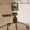
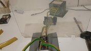
Right now i get 7.41V from transformer, i get about 12V from the rectifier (tested with caps connected). You can see the test setup in the attached image. I used 6 gauge wire for transformer and connections from transformer to rectifier and rectifier to spot welding board. I used 5 gauge wire for the tips. I used thinner wires for caps since i havent assembled a proper bank yet.

Setup as it is right now cant even weld 0.1mm properly. If i use it on a single 0.1mm, it makes a hole, but as soon as i put another sheet of 0.1mm on it, it barely sticks them together.

On highest setting, the voltage drop is such, that the board turns off and on. My solution to this is capacitor with resistor, that keeps the board alive even when everything else drops. Right now its on input of the board, but i could just aswell solder it to the existing capacitor. The only thing i am not sure is whether that capacitor there is a good idea, since as far as i can see, diode comes after capacitor. So that capacitor drops voltage with the weld.

Optocoupler mod you can see near output from spot welding board.

I am wondering whether low voltage also plays a role in bad performance. But i wanted to keep transformer voltage as low as possible to allow more current in that small 700W window. 7V should give me around 100A at transformer output. Besides, i cant possibly do more turns using 6 gauge wire. Nothing in the system gets hot, except the transformer case and battery tab.

20250417_002902.jpg20250417_002908 - Copy.png
 
On highest setting, the voltage drop is such, that the board turns off and on. My solution to this is capacitor with resistor, that keeps the board alive even when everything else drops. Right now its on input of the board, but i could just aswell solder it to the existing capacitor. The only thing i am not sure is whether that capacitor there is a good idea, since as far as i can see, diode comes after capacitor. So that capacitor drops voltage with the weld.
I may be mistaken but I think the aluminium SMD electrolytic capacitor may be connected as shown in the schematic below:

1744848033385.png


If this is the case, the diode and capacitor will help keep the control electronics voltage the same during the weld cycles. If the voltage on the input (anode of the diode) drops, the capacitor will remain charged and will maintain the voltage that was previously there. It doesn't need to be that large, only large enough to supply whatever small amount of current is needed for the control electronics during the welding cycles. If I am correct about this, you should be able to connect another capacitor in parallel with that one to prevent the board from turning off during welding. Can you use a multimeter on continuity check mode to see if the diode and capacitor are connected as they are in the schematic I posted?
 

New Articles From Microcontroller Tips

Back
Top