Continue to Site

Welcome to our site!

Electro Tech is an online community (with over 170,000 members) who enjoy talking about and building electronic circuits, projects and gadgets. To participate you need to register. Registration is free. Click here to register now.

  • Welcome to our site! Electro Tech is an online community (with over 170,000 members) who enjoy talking about and building electronic circuits, projects and gadgets. To participate you need to register. Registration is free. Click here to register now.

bipolar voltage supply with zero crossing (+/- 100V)

Status
Not open for further replies.
No current draw would be simple, a potentiometer across a fixed +-100VDC supply, an LM317 could even provide regulation as long as the voltage drop didn't exceed 40V. 500:mu:A isn't much, I haven't bothered to calculate the error but I imagine that a 20k pot acrosss a +-100V supply drawing 10mA wouldn't give that much of an error at 500:mu:A.

I don't know where you can buy pots rated to 2W at 200V though.

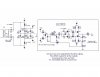
Failing that a DC coupled audio amplifier run from about +-105V would do except you'd have to increase the voltage rating of the transistors, decrease their current rating and increase all the resistor values proportionally.
 
Roff said:
Hero, go for it if you want to. I'm struggling with the following issue...
Dr. Dunk, if the lenses draw zero DC current, the solution should be relatively simple. If not, it seems like it gets complicated.
Don't you have a specification on these lenses?

G'day Roff,

Unfortunately I don't have specifications on the lenses, as they are home built. Check out the pictures I have attached. The first one is the assembly as it is being made, the second is the assembly "in situ" in the vacuum chamber. You are looking for the brass plates (four of them).

Theoretically, the current flow should be zero, as they are insulated from ground by the ceramic insulators that you can see. The design has one threaded rod (Stainless steel) around which a continuous ceramic tube runs. They there are larger diameter ceramic spacers that hold the plates out in space.

Cheers!

P.S. For your information, the other plates you can see are the Time Of Flight plates. They are an integral part of the mass spectrometer. Imagine a burst of ions entering the assembly between the second and third plates (moving directly into the photo). If you pulse a large negative voltage to the second plate in from the right, say -2 kV, and at the same time pulse a slightly less negative voltage to the third plate in, say -1.5kV, this leads to a potential difference of 500V, which serves to eject ions to the left, into the rest of the mass spectrometer! All of this assembly has been home built by our workshop gurus! I already have the fast high voltage switches (from a German company, Behlke) they are MOSFET style.
 

Attachments

  • 28-08-07_0904.jpg
    28-08-07_0904.jpg
    30.6 KB · Views: 203
  • 30-08-07_1614.jpg
    30-08-07_1614.jpg
    25.2 KB · Views: 190
Last edited:
If each of the brass plates is one terminal of a lens, where are the other terminal(s)?
 
Couldn't the flash unit from a disposable camera be utilised for this. These units produce around 300V and with some current limiting resistors and 4 51V zeners you would have a fairly stable supply.

Mike.
 
Roff said:
If each of the brass plates is one terminal of a lens, where are the other terminal(s)?

G'day Roff,
What you do is connect the Vout of one terminal to the lens, while the other is grounded to the machine body. Effectively then, the circuit is not complete as the Vout is isolated from ground (hence the very low current flow).

I will use BNC connections to a vacuum flange. the sheath of the BNC cabling will be terminated to ground (i.e. the flange body)

Does this make sense?
 
Try this out.

Good luck with finding an 80V transformer and a 20k pot rated to 2W though.

Note that it isn't protected against short circuits, at least not for very long periods of time anyway, you can add a 10k series resistor in series with each regulator but it would have to be rated for at least 4W.
 

Attachments

  • 100V PSU.GIF
    100V PSU.GIF
    6.8 KB · Views: 231
Last edited:
Thanks Ron, err I mean Roff I've changed it.
 
Hero999 said:
Try this out.

Good luck with finding an 80V transformer and a 20k pot rated to 2W though.

Note that it isn't protected against short circuits, at least not for very long periods of time anyway, you can add a 10k series resistor in series with each regulator but it would have to be rated for at least 4W.
Why not use 100k pots?
 
The origional requirement was for 500:mu:A so I used 20k because it would give better regulation.

I don't know what the maximum value he can use without any trouble, it depends on the leakage current of the capacitance. He could try 100k or even 1M and probably won't have any problems, experimenting is the best way to tell.
 
Hero999 said:
The origional requirement was for 500:mu:A so I used 20k because it would give better regulation.

I don't know what the maximum value he can use without any trouble, it depends on the leakage current of the capacitance. He could try 100k or even 1M and probably won't have any problems, experimenting is the best way to tell.
From looking at Dr Dunk's assembly, and reading his posts, I'm guessing the current is picoamps. I was gonna propose a 200V shunt regulator that had a "virtual ground" made of a resistive divider, and four 1 Meg pots for the four lenses, but your design is probably simpler. My design does use a small 1:1 isolation transformer instead of an 80V transformer.
 
Hi guys,
Many thanks to Roff, Hero, and all for the ongoing help. You guys are a treasure trove of resources!

One thing to consider. The +/-100V is a nominal value. I put this value, as I thought that any value would be possible to achieve, not realising that it would require a specialised transformer (as per Hero's post). If it simplifies things, then pick any maximum voltage over say 50V, up to 230 V..

Hopefully the value of 100V hasn't lead to head scratching on how to achieve it..

Also, to have four outputs, is it simply a matter of building four such circuits, or could they all be taken off the same transformer?

Cheers!
 
Last edited:
Is there some reason why the power supply out of a disposable camera won't work. In combination with a wall wart it has to be the simplest and cheapest solution. You can even buy the parts at the local grocery store.:D

Mike.
Edit, just looking around I found **broken link removed** Just remove everything to the right of the "large cap" and you have a 200V+ supply.
 
Last edited:
Pommie said:
Is there some reason why the power supply out of a disposable camera won't work. In combination with a wall wart it has to be the simplest and cheapest solution. You can even buy the parts at the local grocery store.:D

Mike.
Edit, just looking around I found **broken link removed** Just remove everything to the right of the "large cap" and you have a 200V+ supply.

Beats me Mike! Thanks for your suggestion, and I will be sure to check it out tomorrow when I get to work (I have gone over my bigpond allowance at home, and I have been dropped to 64 kbit/s... :mad:)
 
You don't need four circuits, just four 20k potentiometers.

Notice that it forms a potential divider which is adjusted by the knob's position?

A capacitor charger might work but it isn't ideal since he wants a regulated supply and it also needs to be capable of producing both positive and negitive voltages.
 
Hero999 said:
A capacitor charger might work but it isn't ideal since he wants a regulated supply and it also needs to be capable of producing both positive and negitive voltages.

A current limiting resistor and 4 * 51V zeners with a center tap on the zeners will give a totally isolated ±100V supply, you can earth the center tap if desired. Although the output voltage will be dependent on the tolerance of the zeners, it will be constant, that is, it may be 105V but will be a constant 105V. Multiple 1MΩ pots could be used to vary the output.

Mike.
 
Pommie said:
A current limiting resistor and 4 * 51V zeners with a center tap on the zeners will give a totally isolated ±100V supply, you can earth the center tap if desired. Although the output voltage will be dependent on the tolerance of the zeners, it will be constant, that is, it may be 105V but will be a constant 105V. Multiple 1MΩ pots could be used to vary the output.

Mike.
I started out thinking zeners, but the tempco of the standard ones are higher than the OP was looking for. There are compensated zeners available, but I thought they might be difficult to obtain (or hard to get :D).
 
As the current is so low then the zeners shouldn't get hot and the Tc in the first data sheet I found (BZX79C51) was 40mV/°C. If you choose the current limiting resistor correctly then most of the current will flow through the output pots. If nothing else, it's cheap and can be tried easily.

DrDunk,
You state 0.1% variation over the day. Is this realistic as I doubt that you can position a pot to better than 1%.

Mike.
 
Pommie said:
As the current is so low then the zeners shouldn't get hot and the Tc in the first data sheet I found (BZX79C51) was 40mV/°C. If you choose the current limiting resistor correctly then most of the current will flow through the output pots. If nothing else, it's cheap and can be tried easily.

DrDunk,
You state 0.1% variation over the day. Is this realistic as I doubt that you can position a pot to better than 1%.

Mike.

G'day Mike,

It is an ideal.. I suppose that +/- 1V would also be acceptable, however if it was to drift throughout the day, then this would not be good. As the electrostatic lenses are used to deflect a beam of ions, any drift in the voltage would mean that the ion beam would shift off axis and not pass through the machine..

BTW, in the interest of giving you all a better understanding, I have attached a pdf schematic of the machine I am building. The parts that we are discussing are in the "extraction chamber". The chambers shown are all vacuum chambers, with resting vacuum of better than 10^-6 torr (for reference you are sitting in around 760 torr right now)

Apologies that this is outside the scope of "electronics" however thought that you may be interested..

The machine is a time of flight (TOF) mass spectrometer coupled to a photoelectron spectrometer (the long tube). In a nut shell, ions and cluster ions are produced in the ion source, accelerated along the TOF axis, and overlapped with laser radiation in the "Laser interaction chamber". In this region, electrons are forced off the anion clusters, and are directed along the flight tube. We measure their energy, which is related to their molecular origin! With this machine it will be possible to follow the course of chemical reactions!

Anyway, as I said it is outside the scope of this forum, however it has some nice applications of electronics associated with it.

Cheers!
 

Attachments

  • ModifiedSetup.2.pdf
    19.4 KB · Views: 192
Last edited:
Status
Not open for further replies.

Latest threads

New Articles From Microcontroller Tips

Back
Top