Continue to Site

Welcome to our site!

Electro Tech is an online community (with over 170,000 members) who enjoy talking about and building electronic circuits, projects and gadgets. To participate you need to register. Registration is free. Click here to register now.

  • Welcome to our site! Electro Tech is an online community (with over 170,000 members) who enjoy talking about and building electronic circuits, projects and gadgets. To participate you need to register. Registration is free. Click here to register now.

Bode plot of B-branch

00don00

New Member
Hello all,
Sorry for interrupting, but I have some troubles with plotting bode.

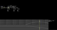
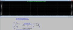
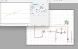
Namely, the picture below shows my oscillator( he is oscillating properly at fruequency of 14.Mhz for which I need to find the transfer function (draw a bode diagram). I need to get the transfer function of the beta branch to see what it looks like and why it oscillates at 14MHz.
Now, trying, I don't know where I'm going wrong, picture 1 in the attachment is the whole circle, and picture 2 is the B-branch.
1f.png
2f.png
 
Last edited:
Its tricky as you break the loop with your XBP2 setup, so the loading of the input and
output of the freq determining network is not accurate. And you have not shown the
parasitics for the bipolar, like miller C and varies junction C.

That being said you can do an approximation with some assumptions :

1) Look at just the network consisting of the xtal and its 12 pF loading caps. In
simulator drive input to it with a current source, and using hybrid pi model
approximation calculate Zin of the transistor and use that for loading across the
output 12 pF. Then look at sim plots for when the phase shift becomes 180 degrees.

OR

2) Use signal flow graph (SFG) approach to evaluate the entire circuit input to xtal to
output at collector of transistor, and that will get you in ballpark. Here you
would look for 360 degrees of phase shift. Tedious but SFG makes it a lot
easier for high order networks. Search web and you can find GUI utilities
to construct the graph and its tool will generate the T(s) for you.


Regards, Dana.

Three differents simulation tools are giving me three different results.. frequency should be around 14.2Mhz.
What am I doing wrong?
 

Attachments

  • WhatsApp Image 2024-09-09 at 22.19.21.jpeg
    WhatsApp Image 2024-09-09 at 22.19.21.jpeg
    51.2 KB · Views: 24
  • WhatsApp Image 2024-09-09 at 22.18.38.jpeg
    WhatsApp Image 2024-09-09 at 22.18.38.jpeg
    185.3 KB · Views: 22
  • WhatsApp Image 2024-09-09 at 22.14.10.jpeg
    WhatsApp Image 2024-09-09 at 22.14.10.jpeg
    195.4 KB · Views: 22
1725923930878.png


The freq is off because the input z does not reflect its loading due to transistor collector.
Same is true for output loading, the miller C generated by transistor not present.

Using just the L and .01pF that resonant freq is ~15 Mhz. You sure you have the correct
values for the crystal model ?


Regards, Dana.
 
View attachment 147062

The freq is off because the input z does not reflect its loading due to transistor collector.
Same is true for output loading, the miller C generated by transistor not present.

Using just the L and .01pF that resonant freq is ~15 Mhz. You sure you have the correct
values for the crystal model ?


Regards, Dana.
l see, it's clear to me now.
And how will I find the transfer function of the beta branch (my first question)? I get a little lost in the laplace transform.....
 
You write node and branch equations and do the algebra.

Or use SFG and one of the utilities and it will generate it for you.
 

Attachments

  • sfg.js-master.zip
    32.3 KB · Views: 30
View attachment 147062

The freq is off because the input z does not reflect its loading due to transistor collector.
Same is true for output loading, the miller C generated by transistor not present.

Using just the L and .01pF that resonant freq is ~15 Mhz. You sure you have the correct
values for the crystal model ?


Regards, Dana.
But why then my oscillator is oscillating at 14.2MHz?
 
You write node and branch equations and do the algebra.

Or use SFG and one of the utilities and it will generate it for you.
I still don't undarstand ( for node and branch equations), and I think that's my problem with Laplace.
What is correct node and branch equation for my B branch above?

Earlier, I found this transfer function, for simmilar oscillator:

1725950383163.png
(1)
where
1725950474135.png
(2)
C- series capacity of quartz crystal(0.01pf)
Co-paralell capacity of quart crystal(1pF)
C2- 12pF
 
Last edited:
This is where I got stuck, i will attach ac equivalent with hybrid model here. And some equations that I've done.
At the end I have to find an frequency analytically of my circuit.- to proove where it is oscillating (at 14.2Mhz - calculating the transfer function i suppose)
IMG_3404.jpeg

This Z1+Z2+Z3=0 is the equation from which I need to express the frequency and should get the oscillation frequency, if I'm not mistaken
 

Attachments

  • image.jpg
    image.jpg
    1.4 MB · Views: 24
Last edited:

Latest threads

New Articles From Microcontroller Tips

Back
Top