Electro Tech is an online community (with over 170,000 members) who enjoy talking about and building electronic circuits, projects and gadgets. To participate you need to register. Registration is free. Click here to register now.
Welcome to our site! Electro Tech is an online community (with over 170,000 members) who enjoy talking about and building electronic circuits, projects and gadgets. To participate you need to register. Registration is free. Click here to register now.
Q2 base emitter junction connects the supply directly to the top of R2, so the emitter of Q1 is only 0.7V below it's collector, with 2.3V just wasted across R2. I'm doubtful if it will work on only 0.7V, but in any case why use a 3V supply and throw 2.3V of it away?
Your question is lacking some important information, such as What is the circuit supposed to do? What are the inputs and where are they connected? What is the output and where is it connected?
I have added 10uF input and 100uF output cap to LT1086 voltage regulator.
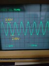
Oscillations still here, but its frequency drops to 15.86MHz.
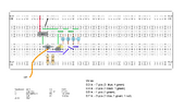
Also I have checked values of inductors and capacitors from LC tank with RLC meter, and it confirms why oscillations is about 16MHz but not 26MHz:
Ideal: L1 = 1uH||10uH||10uH||22uH = 803nH, C1 = 47pf ==> Fres = 25.907 MHz
Real: L1 = 3uH||10.2uH||10.2uH||21uH = 1733nH, C1 = 56pf ==> Fres = 16.156 MHz
(My 1uH inductor acually is 3uH...and 47pf cap is actually 56pF...)
Also without C1 capacitor, only breadboard parasitic capacitance left, frequency is 20.77MHz.
According to tank frequency formula it means that parasitic capacitance between three rows on my breadboard is 34pF, but I think it is too high capacitance, maybe 20.77MHz is a limit of frequency 2N2222 can support?
This site uses cookies to help personalise content, tailor your experience and to keep you logged in if you register.
By continuing to use this site, you are consenting to our use of cookies.