Continue to Site

Welcome to our site!

Electro Tech is an online community (with over 170,000 members) who enjoy talking about and building electronic circuits, projects and gadgets. To participate you need to register. Registration is free. Click here to register now.

  • Welcome to our site! Electro Tech is an online community (with over 170,000 members) who enjoy talking about and building electronic circuits, projects and gadgets. To participate you need to register. Registration is free. Click here to register now.

Can You figuire out this circuit Schematic?

Status
Not open for further replies.

Engjay

New Member
hi Guys
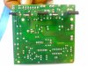
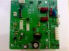
can anybody figure out what does this circuit do ?
i toke it from a tradmill near the dc motor
i want to know where the dc part is in this circuit
i need the schematic form for this circuit
i will attach the picture hope it can help
if u know any circuit that is similar to it
the names of the 6 chips
1-mospec u16c60c
2-kia 7805pi
3-cd 40106be h9605
4-ixys dsei 30-06A
5-st mrc tyn690
6-s21md3v sharp
thanks
 

Attachments

  • qqq.jpg
    qqq.jpg
    95.2 KB · Views: 327
  • 07032008277.jpg
    07032008277.jpg
    90.8 KB · Views: 277
An easier way to figure out the circuit is to hold the PCB up to a very bright light while looking at the parts side. Then you can see the copper traces through the PCB and draw out a schematic yourself. No one is going to do it for you. You could also mirror the picture of the foil side in photoshop and place it next to the unmirrored parts side picture, but again, no one is going to do it for you. :rolleyes:
 
Why have the transistors been reomved and remounted on the other side of the PCB?
 
Hero999 said:
Why have the transistors been reomved and remounted on the other side of the PCB?

What makes you think they have been removed and remounted?, I would imagine it was made like that, in order to fit a specific casing and heatsink.
 
It looks very similar to boards use on stepper motors I think there Phase modulated. Somewhat like a Dimmer pack maybe for lighting circuits ?
 
Now that I remember look up dayton control circuits it might get u a little closer.
 
The KA 7805 should be the regulator Probably 12vdc. Your AC input by the fuse is then sent to the Diodes near it to be rectified. After that I'm not sure without a schematic.
 
Status
Not open for further replies.

New Articles From Microcontroller Tips

Back
Top