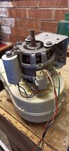
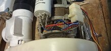
Hi - I am just here to ask for help with my Candy tumble dryer motor, which I have extracted and wish to use in a project. The windings have three wires coming out: Orange, Blue, and Grey. The motor works with just the orange and blue connected to the mains supply (live and neutral), with the grey not connected to anything. It doesn't self-start, but it runs once I give it a spin.
The capacitor appears to be OK (still not sure) so it seems likely that the lack of self-starting is because of the grey wire not being connected to anything.
How should I connect the grey wire? Bearing in mind that the motor is to be used externally, not back in the original dryer.
Many thanks
The capacitor appears to be OK (still not sure) so it seems likely that the lack of self-starting is because of the grey wire not being connected to anything.
How should I connect the grey wire? Bearing in mind that the motor is to be used externally, not back in the original dryer.
Many thanks