Continue to Site

Welcome to our site!

Electro Tech is an online community (with over 170,000 members) who enjoy talking about and building electronic circuits, projects and gadgets. To participate you need to register. Registration is free. Click here to register now.

  • Welcome to our site! Electro Tech is an online community (with over 170,000 members) who enjoy talking about and building electronic circuits, projects and gadgets. To participate you need to register. Registration is free. Click here to register now.

Capacitor to be used for filtering DC noise

Status
Not open for further replies.

lloydi12345

Member
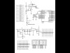
I have successfully made my temperature controller but there's a problem. With a 320°F setup using a temperature calibrator machine. While my thermistor probe placed in the machine my controller detects it quite well with a maximum error of 1°F. Sometimes it is 321°F sometimes it is 320°F. Now the problem is that randomly in 15 mins, 30 mins, 40 mins, 1 hour or even two (no particular time really), the temperature display changes to values higher or lower than the real temperature values by 10 values(numbers between 310°F and 330°F). What I'm doing to fix this is to turn off the circuit and turn it on again then everything will go back to normal. I don't think this is right. I think the cause of this problem is the noise but I can't figure out what type or value of capacitor I should use. Maybe it's not the noise. I might missed something. I attached my schematic below. C5 is the ceramic cap near the microcontroller.

I measured the value of the ADC voltage fed to the microcontroller and it's a stable voltage. It doesn't change even a millivolt.

I tried a trial and error approach just hoping this as my lucky day. I waited for the values to fluctuate then I tried plugging at 7805's output pin capacitors like 10uF. The temperature value slowly crawled to the actual temperature. So I soldered it thinking it's the right value but after again some random time the temperature value jumped again. I even tried 22uF and 220uF all rating 25v. Does the voltage rating affect the circuit?

I badly need some helping hand :(

Regards,

lloyd
 

Attachments

  • Schematic.pdf
    42.6 KB · Views: 177
Last edited:
How about connecting a 10nF capacitor in parallel with the temperature sensor?

Boncuk
 
There seems a serious lack of decoupling on the circuit? - and both the relay and LED display will need decent sized electrolytics across their immediate supply pins, and 0.1uF near the PIC.

R29 is also shown as massively too high, and you're showing an AC voltage feeding the circuit (which presumably is incorrect).
 
How stable is your Vref (pin 5)?

Ron
 
I forgot to tell everyone J3 connector is connected to the relay.

How about connecting a 10nF capacitor in parallel with the temperature sensor?

Boncuk

I'll try this one.

There seems a serious lack of decoupling on the circuit? - and both the relay and LED display will need decent sized electrolytics across their immediate supply pins, and 0.1uF near the PIC.

R29 is also shown as massively too high, and you're showing an AC voltage feeding the circuit (which presumably is incorrect).

What values can you suggest to place on the 7segments and relay? Sorry the diagram was incorrect. It should be 24vdc I'll edit it. Any suggestion also for the value of R29?

How stable is your Vref (pin 5)?

I forgot. Vref wasn't connected since I'm using the power pin of the microcontroller as the Vref which I set in the software. I don't know if it is stable.
 

Attachments

  • Schematic.pdf
    41.8 KB · Views: 141
Last edited:
25 ma of zener current would make r29 about 470 ohms 1/2 watt.
 
Hi ronv :) what will happen if it is 100k? the transistor will limit more voltage from 24Vdc or lesser? Right now the voltage produced on the emitter is 11.5vdc
 
The TIP31 has a Typical current gain of 100 at low currents. So what will happen is that when the current goes above 12 ma the voltage will begin to fall. 12v / 100k X100 = 12 ma. Also if you check the zener spec you will see it is tested at 21 ma. That is probably why your reading is a little low.
This may not be your problem, but it might well be as the ref voltage will change depending on the load.

Thanks ronv but this only applies on the input of the 5v regulator. Gonna have to try on the output part something else. :(
 
The datsheet doesn't seem to specify it, but it does have a parameter "Bias current" which is 4.3 mA which MIGHT BE minimum load. So does your 5V supply see at least 4.3 mA at all times?
 
I tried 10nF but didn't work. :(
 

Attachments

  • schematic.JPG
    schematic.JPG
    123.9 KB · Views: 194
Last edited:
I don't think I can place a capacitor for the 2 dual 7seg display since it is directly supplied to the microcontroller through resistors without any driver IC. What capacitor could I use for Omron MY4N relay??? Will my elec cap 10uF be enough? I'm using 30vdc to turn it on. I measured the voltage on the relay power. When the relay is off it is 30.7v and if the relay is on voltage drops to 29.4v.
 
Last edited:
Status
Not open for further replies.

Latest threads

New Articles From Microcontroller Tips

Back
Top