If you are detecting signals within one of the Amateur bands, then something must be transmitting them?
That transmitter must comply with the national licencing rules - power, frequency, spurious emission and
identification in every transmission:
As Nigel says, any superregenerative receiver can be very dodgy item - they can be used and sold commercially, but each specific type needs FCC or equivalent certification before it can be sold, to ensure it does not cause harmful interference.
Equipment you build yourself for use in the Amateur bands is exempt from the certification rules, but it's also a part of the Amateur licence conditions that you test any device you build to ensure there are no spurious emissions at unreasonable levels.
Superregen types are quite common in simple DIY Amateur band receivers, but need extremely careful setting up to avoid problems.
Re. modifying commercial devices, the ones we have used in products have been FM types and all have SAW filters to define the operating frequency so they could not be modified. They are also vastly more complex than any cheap ebay modules.
The ones we have used are similar to such as this
http://www.radiometrix.com/wrx2-0
I know there are a lot of cheaper & lower quality ones about, but I do not know offhand just how practical they are to mod for a drastically different frequency.
>google<
It looks like there are two very common types of cheap AM / OOK 315 & 433 MHz receiver modules on ebay.
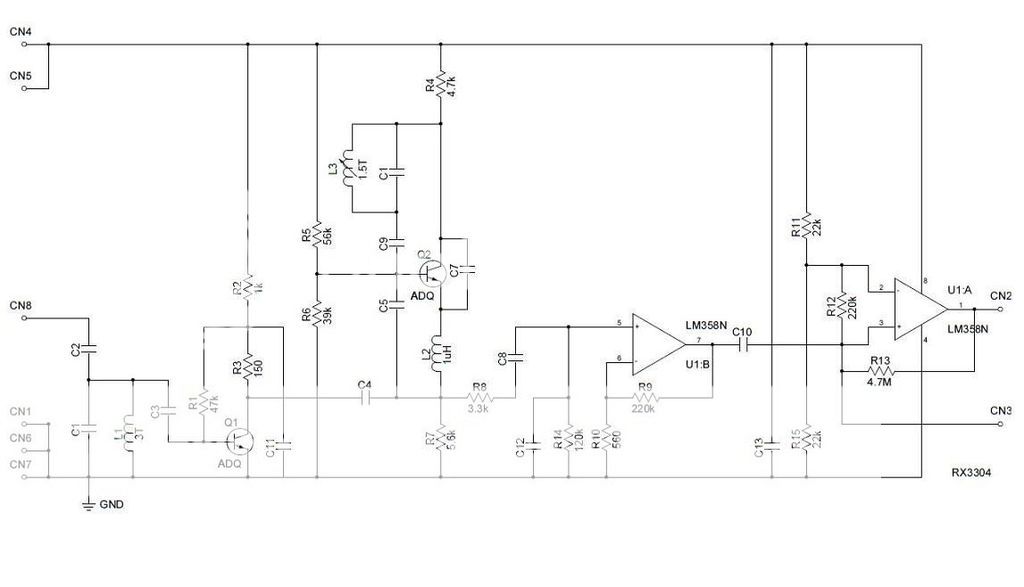
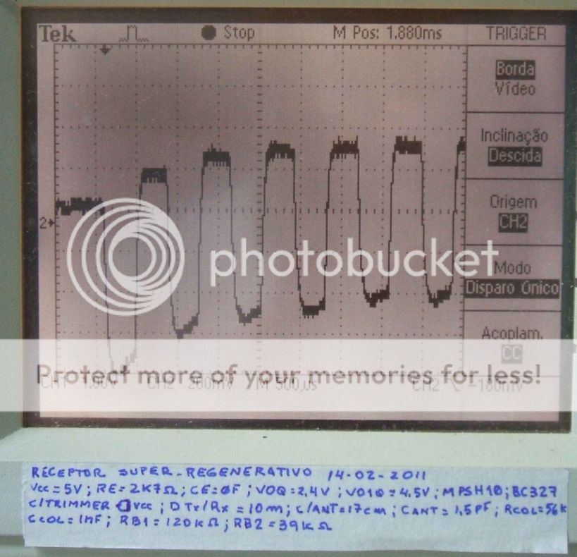
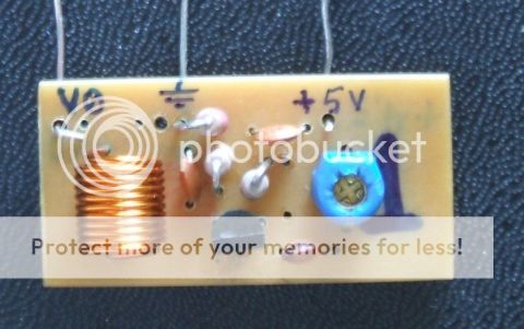
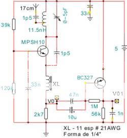
The simpler ones are superregenerative, and the circuit for those is freely available.
The transmitters are SAW based but the receivers just use a couple of tuned circuits.
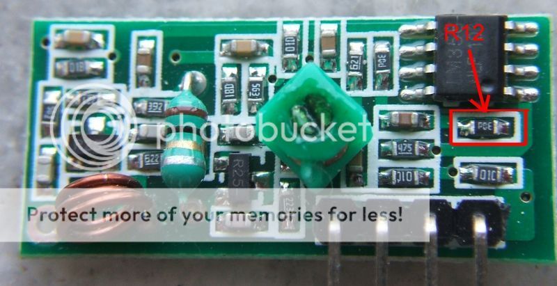
Pictures and schematics in this listing:
http://forum.hobbycomponents.com/viewtopic.php?t=1324
Modifying those receivers for 2m should be a doddle, but I'd not use them after modding until I'd very thorough checking for spurious output - and there is no way of knowing if they are even legal in the first place.
In fact that seems very unlikely - looking up their type number "MX-05V" brings up masses of similar items, but nothing like them if searched for in conjunction with FCC ID or Type approval (The UK certification).
Personally I'd put it in a die cast box with an antenna connector screwed through the wall & filtered signal connections, no matter what other testing I did!
The other common ones are superheterodyne modules and slightly more sophisticated - but the receiver IC they all seem to use is designed for the 300 - 440MHz range, so they cannot be re-tuned to 2m.
eg. These
**broken link removed**
Which use this device:
If you want a decent, simple, 2M AM receiver, look at something like this - two ICs and a few components:
Or, a simple tuned front end and mixer that shifts the 2M signal to either 315 or 433 so one of the cheap superhet modules can be used as first IF and demodulator???
[Also with two Amateur licences - G8TBF & G0WTK].

