Could somebody check my first attempt to convert electronic circuit to breadboard schematic? I have created it with DIYLC application.
Here is the schematic:
https://www.electro-tech-online.com/attachments/vu-meter2-png.44078/
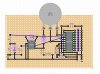
Here is my conversion:
https://www.electro-tech-online.com/attachments/vu-meter-layout-jpg.68823/
The blue lines are jumper wires.
In case somebody wants the original file, here is the DIYLC diy file:
https://www.electro-tech-online.com/attachments/led-vu-meter-layout-txt.68824/
Just need to change the extension from txt to diy as I couldn't upload diy files.
Thanks.
Here is the schematic:
https://www.electro-tech-online.com/attachments/vu-meter2-png.44078/
Here is my conversion:
https://www.electro-tech-online.com/attachments/vu-meter-layout-jpg.68823/
The blue lines are jumper wires.
In case somebody wants the original file, here is the DIYLC diy file:
https://www.electro-tech-online.com/attachments/led-vu-meter-layout-txt.68824/
Just need to change the extension from txt to diy as I couldn't upload diy files.
Thanks.