Follow along with the video below to see how to install our site as a web app on your home screen.
Note: This feature may not be available in some browsers.
For DS8, and any other members who are interested in the schematic and some photo details.
For the tank Capacitors it is better to use a lot of Capacitors in parrallel, better with current sharing and heat dissipation. ( I used here 1 x 470 nF and 8 x 47 nF in Parrallel ) The 470 nF gets hot when run at 24 Volts for a longer time.
Keep the leads short between this Cap and the LOPT 5 + 5 or 6 + 6 coils.
The coils are wound in the same direction with a centre tap. e.g. 10 turns with centre tap makes 5 + 5.
Wire size I used here was 1 mil². running current about 5 Amps at 24 Volts.
The red LED is an indication, so I know the coil is oscillating. just 2 turns a LED and 1 k.Ohm R in series.
I use this driver now to power a simple Tesla Coil which works very well.
( I will make up an other thread with more details if members are interested. )
During testing, especially first test run, put a 12 V 50 or 100 Watt car head light in series. saves blowing up the mosfets in case of a wiring error.
A 10 or 16 Amp HRC fuse is also good to fit in the positive line.

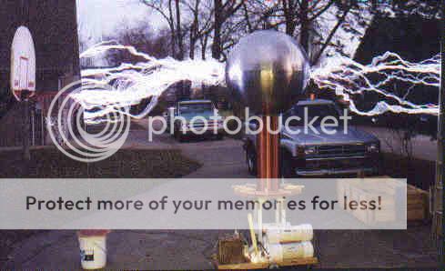
Is that first pic photoshopped?
Nice, Gary. I was wondering what you were up to; and now I know you still at it.
How did the Induction Heater go?
kv
The induction heater when up in smoke. LOL. Mosfets went BOOM then all 5 bridge rectifiers went BOOM. I saved the LC coil with capacitors, filter caps, heat sink, transformer. The rest went in the trash cans.
