Electro Tech is an online community (with over 170,000 members) who enjoy talking about and building electronic circuits, projects and gadgets. To participate you need to register. Registration is free. Click here to register now.
Welcome to our site! Electro Tech is an online community (with over 170,000 members) who enjoy talking about and building electronic circuits, projects and gadgets. To participate you need to register. Registration is free. Click here to register now.
I have a problem with a circuit, I am not getting supply voltage to the receiver circuits.
The circuits consists of two remote transmitters & two receiver circuits that operates some 12v relays, two channels.
It was working fine & then suddenly both channels became inoperable at the same time.
Upon inspection there is no supply voltage at the receiver circuits.
Could someone help me sort this issue out, my electronics knowledge is not good but I would like to fix this with some assistance.
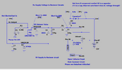
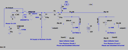
I have attached a rough schematic, the datasheet for the receiver circuits & the datasheets for the relays.
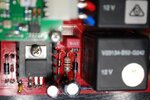
The relays are No V23134-B52-G242.
Receiver Circuits are MCR91502P
I first tested the voltage regulator from the input pin to the ground pin & there was continuity so I unsoldered the input pin & tested it again with NO continuity between the input pin & the ground pin so it appears to be ok.
Edit:
I made an error in the first schematic I had D2 & D5 orientation the wrong way, my bad!
I found some information on some fuse codes vs ratings & the G = 0.75A, F meaning Fuse on the site I looked at?
I have continuity across the component.
I found some information on some fuse codes vs ratings & the G = 0.75A, F meaning Fuse on the site I looked at?
I have continuity across the component.
That would appear to be OK then, however your 'test' of the voltage regulator above is meaningless - you can't test a voltage regulator on ohms - you need to measure the voltages going in and coming out. Ohms ranges are fairly rarely used in fault finding, other than for testing fuses, or perhaps rectifiers or power transistors.
That would appear to be OK then, however your 'test' of the voltage regulator above is meaningless - you can't test a voltage regulator on ohms - you need to measure the voltages going in and coming out. Ohms ranges are fairly rarely used in fault finding, other than for testing fuses, or perhaps rectifiers or power transistors.
That would appear to be OK then, however your 'test' of the voltage regulator above is meaningless - you can't test a voltage regulator on ohms - you need to measure the voltages going in and coming out. Ohms ranges are fairly rarely used in fault finding, other than for testing fuses, or perhaps rectifiers or power transistors.
Thanks Nigel, I understand now about the voltage regular tests, it was just the input on the regulator has a dead short to ground when connected in the board. I assumed that it maybe could have a short so I removed the input leg from the board & then tested it again. There appears to be a short to ground somewhere as described in the schematic I posted hence 0v to the input of the regulator & no voltage out to the receiver supply connection.
Where do I start to test for shorts?
Do I have this correct in the way this circuit works.
One side of the coil in the relay is connected to 12v via pin 86, the signal from the transmitter ( Remote) is received by the receiver circuit & the output of the open collector circuit goes to ground energizing the relay coil via pin 85.
From those voltage measurements the fuse is definitely blown, and I presume R1 isn't actually 1K?, it's more likely a small inductor, and will have a very low DC resistance. Most likely cause of a short would be D5 (over volts zener) or the two electrolytics C1 and C2.
When you say a short to ground what value resistance reading do you get ?
My undestanding is that the 12 volt battery on the right hand side is the power source for the circuit. This passes through the "GF" component which is probably a fuse. (It could be a low value inductor used as a noise filter.) As you have 11.2 volts across the"GF" component it must be open circuit. D3 will be a reverse polarity protection diode.
On the assumption that there is NOTHING ELSE connected to D3 cathode other than that shown in your circuit then I would suspect that C1 is short circuit.
As there is a 1K resistor between TP3 and TP4 you must have two shorts. This is why I asked how low a resistnace that the shorts are.
Edit. I have just seen Nigel's post #33. R1 being an inductor makes more sense than it being a 1K resistor. If it is an inducter it will probably have a very low resistance which would expain why you get two apparent shorts to ground.
Firstly, Thanks to everyone for the help with this.
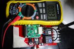
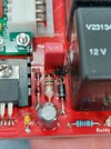
Ok, I checked the resistance between the ground input to the board & the regulator input leg, please see picture.
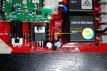
I have included the picture of what I assumed was a resistor but I think Nigel is correct that maybe it is an Inductor, please see the other picture as well.
The resistance across this component as is on the board is only 0.5 Ohms.
I just looked at the 4 Band colors ?
There was a new 12v car battery fitted to this machine & now I am wondering if they haven't connected it in reverse polarity & are just telling me it just stopped working?
I have found the short in the D5 Zener Diode.
It is a C20PH 0.5w
What would be the lowest Voltage Zener that I can use our local stores only stock 1W Zeners as well is this ok.
I Have some 1N4749 1 Watt Zeners but the rating is a little higher.
I have found the short in the D5 Zener Diode.
It is a C20PH 0.5w
What would be the lowest Voltage Zener that I can use our local stores only stock 1W Zeners as well is this ok.
I Have some 1N4749 1 Watt Zeners but the rating is a little higher.
It's an over volts zener (which was why I listed it as the most likely problem), so the wattage doesn't matter much, it's there to blow the fuse if the input voltage is too high. A 1 watt zener will still blow the fuse, but is less likely to die itself.
It's a 20V zener, and needs to be, but a 1 watt 20V zener will be fine.
For testing purposes you can just remove the zener, replace the blown fuse, and ensure everything works OK - fit a new zener before finishing the job though.
I powered up the circuit with the Zener out & to my surprise the power light is on & I have 9v to the receiver circuits, it appears that the fuse is not blown?
I certainly have 12v on either side of the fuse now.
Why is the fuse not blown with a dead short to ground through the Zener diode?
Not sure I understand that!
Edit:
Maybe the component is not a fuse but a "surge protector", does that make sense?
My other question is the cause of this issue, would it be inductive spikes from the relay coils?
If so can I add a flyback diode across the relay coils or somewhere else, I have some MUR 1560 Ultrafast diodes, datasheet attached?
Or a 470 Ohm resistor across the relay coils.
I have attached the wiring diagram of how both relays are connected.
I have found a picture of another similar board on the net that has had issues as well, attached, it seems to be a problem.
This site uses cookies to help personalise content, tailor your experience and to keep you logged in if you register.
By continuing to use this site, you are consenting to our use of cookies.