Continue to Site

Welcome to our site!

Electro Tech is an online community (with over 170,000 members) who enjoy talking about and building electronic circuits, projects and gadgets. To participate you need to register. Registration is free. Click here to register now.

  • Welcome to our site! Electro Tech is an online community (with over 170,000 members) who enjoy talking about and building electronic circuits, projects and gadgets. To participate you need to register. Registration is free. Click here to register now.

Connection From Welder To Generator

Status
Not open for further replies.

youthenme

New Member
Please let me know if this question is posted in the wrong location. I am new and this was my best guess.

The situation
I have a heavy duty electric cord with the proper connection to connect my welder to my generator.

Unfortunately, the welder is a three prone and it needs to connect to the plugin that goes into a four prone outlet on the generator.

My question
How do I hook up the three prone to the four? From the schematic I can tell which is the ground. So I know that from the three prone welder I hook the round ground to the "G" ground on the generator.

What do I do about the other two wires :confused:

Any help would be really amazing since I am pretty confused about the hookups.

For reference

The three prone looks like this. It is a Lincoln Electric AC-225C Arc Welder.
3prone_small-jpg.43352


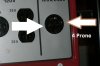
The outlet that I want to convert to looks like this. It is a Honda Model EM5000SX Generator showing the 240 Volt outlet.
4prone_small-jpg.43353


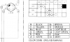
A clip of the schematic of the Honda generator:
schematic_part-png.43354
 

Attachments

  • 3prone_small.jpg
    3prone_small.jpg
    35.7 KB · Views: 1,652
  • 4prone_small.jpg
    4prone_small.jpg
    64.4 KB · Views: 5,915
  • schematic_part.png
    schematic_part.png
    27.1 KB · Views: 2,259
Last edited:
On the generator, you will find 240Vac between Blue and Red. White is Neutral, meaning that there is 120Vac between White and Blue, and between White and Red. Green is frame ground.

On the welder, there should be 240Vac between the two angled prongs (L1 and L2). The Lshaped prong is frame ground (Green/Gnd). There is no connection to Neutral needed by the welder.

I would buy a four prong plug to match the generator. I would buy a Range or Dryer receptacle at Home Depot, and make a short adapter using #10AWG wire. Only three wires need be connected.
 
Last edited:
the reason is because the national electrical code use to allow dryers, ranges, welders etc to share the grounded conductor (neutral) now it was found people were getting shocked if the neutral lifted off and they were caught between current contacting the frame a person could complete the circuit to ground, so now everything is grounded seperate and no more "sharing" the neutral except in the case of service equipment, even the generator outputs use to be a simple 3 wire and we considered them seperatly derived systems and treated them as basically a little service 120/240 but now its all seperate, green or bare is to the metal conductive frame, the neutral is the neutral white or natural grey only and whats left are your remaining phases A & B which can be any color except green, white, or natural grey.
 
Thanks Mike - This was exactly what I was needing to know!

Thanks jbelectric777 - very interesting to know! Makes more sense on why it is different now.
 
Last edited:
One problem that I see is the receptacle is rated at 20amps and the welder has a 50 amp plug on it.
Your generator doesn't provide enough current to power the welder, it wil turn on but you won't be able to weld at anything much over 60 amps or so. The L14-20 on the schematic designates it as a 20a device.

Uh, good point! Here (attached) are some specifications on the welder.

Ron
 

Attachments

  • Welder 225.jpg
    Welder 225.jpg
    34.4 KB · Views: 340
Status
Not open for further replies.

Latest threads

New Articles From Microcontroller Tips

Back
Top