Continue to Site

Welcome to our site!

Electro Tech is an online community (with over 170,000 members) who enjoy talking about and building electronic circuits, projects and gadgets. To participate you need to register. Registration is free. Click here to register now.

  • Welcome to our site! Electro Tech is an online community (with over 170,000 members) who enjoy talking about and building electronic circuits, projects and gadgets. To participate you need to register. Registration is free. Click here to register now.

Controlling multiple outlets with SSR Relay module and Arduino

nicofiaba

New Member
Hi everyone. For my "meat aging machine" project I need to turn on and off multiple devices remotely according to the value of temperature ad humidity read by a sensor. I want to make a power strip with 4 outlets. I want to control each of those with a solid state relay (I have a module of 4). Is it safe to wire it like I show in the figure below? The solid state relay module will be in a separate box and Arduino will be in a third box. My concern is about those 5V, GND and signal cables that go from the 220AC box, where the relay module is, to the 5V Arduino box. Is there any way to wire this more safely? Sorry for my ignorance, I'm here to ask you since I don't want to hurt myself. Thank you very much in advance.
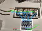
 

Attachments

  • IMG_20240131_2308562.png
    IMG_20240131_2308562.png
    953.7 KB · Views: 518
The Arduino is optically isolated from the loads (and power) being switched. There's no danger of shock from the Arduino board. There is a shock danger from the SSR board. The high voltage connections are exposed on the back of the board so it should be anchored down to prevent a shock when it starts to fall and without thinking you reach out to grab it.
For this reason, I'll make a hole in the two boxes and screw them together so that the cables exiting the outlet box are immediately entering the relay box.
 
Yes the SSR board must be enclosed in plastic/insulated to become "double insulated" yet not create a thermal problem from the enclosure.
What do you mean by "double insulated"? I was thinking about mounting the relay board on insulating plastic spacers inside a plastic box. Do I need to add another plastic box inside the main one?
 
normally , no.
All non-PE grounded products must have "double insulation". in this plastic spacer/case + Opto Triac = 2 insulators.
 
Hi again everyone! I managed to control the outlets via the SSR module. But here comes a problem: In order to keep the temperature to a constant value (with some tolerance), I need to control a refrigerator. Arduino is successfully switching the SSR on and off accordingly to the temperature read by a sensor but probably the amount of current needed to start the refrigerator is overcoming the 2A maximum current supported by those relays and the fuse on the board burned. How can I replace that relay? I thought about a standard relay module (the blue ones) that can support up to 10A current but some people report failures after some time, or a big SSR like the one in the picture below. Is it safe to use? Is the DC part well isolated from the 220V one? What would you recommend? Thanks a lot.
Screenshot_2024-03-03-20-45-34-089_com.amazon.mShop.android.shopping.jpg
 
A fridge/freezer does take a lot of current at start up, so thats why your 2A SSR blew its fuse etc.

A 10A SSR circuit is very similar to the 2A type. We use them for our bigger heaters.

Your firdge should have a label on it indicating its power needs in Amps or Watts, probably well under 10A apart from the start up surge.

However some of those unbranded far east SSRs can be lower quality so we would choose a 25A type which are a similar price. to the 10A ones, Quality branded SSRs like Crydom cost many times more.

Note that the back of these bigger SSR have a flat metal back designed to be screwed to a metal case or heatsink as when handling larger currents they can get warm or even hot.

Take great care as you are dealing with mains high voltage and high current devices or get a qualified electrician to do it for you.
 
Thank you for your reply. If I decide to go for the 25A SSR, since I will never use more than maybe 2A apart from the start up surge, can I place it in a plastic electrical box? Will a NOT SSR board, rated for 10A, work for me? I'll check later the specs of my fridge. Thanks a lot.
 
Thank you for your reply. If I decide to go for the 25A SSR, since I will never use more than maybe 2A apart from the start up surge, can I place it in a plastic electrical box? Will a NOT SSR board, rated for 10A, work for me? I'll check later the specs of my fridge. Thanks a lot.
Specs won't help, they don't details of the switch-on surge.

Also building a device that has multiple outputs, all with puny capabilities, is asking for trouble.
 
Three out of four outlets are used for devices that are drawing, at maximum, 0.5A (A light bulb). The only problem I'm facing is with the refrigerator. What would you do to tackle this problem? I've seen there are mechanical relay boards (SLA model) that are rated for 30A and that are opto-isolated. Safety is my first concern, that's why I'm asking before trying with any relay I find on Amazon.
 
IMG_20240304_115823.jpg

Just for the sake of completeness, this is the device I built. Inside a refrigerator we have a ultrasonic humidifier, a dehumidifier and a light bulb as heating source.
IMG_20240304_115839.jpg

This is the control panel (opened) at the side of the refrigerator, an Arduino Nano is keeping temperature and humidity to a constant value by switching the devices on and off via the relay module you can see in the next picture (the Songle relay here is just for the simulation of the button press on the humidifier (12V, not AC)).
IMG_20240304_120012.jpg

The wires on the right, coming from the control panel, are powering the relay module and sending the switching signal to the 4 relays. the live wire (brown) from the 4 outlets is going to the AC side of the SSR module. The one i burned and that I need to replace is the first from the left, where the refrigerator is plugged in. Notice that this AC box has a cover, despite transparent. The refrigerator is quite small as you can see from the first image.
 

Latest threads

New Articles From Microcontroller Tips

Back
Top