Continue to Site

Welcome to our site!

Electro Tech is an online community (with over 170,000 members) who enjoy talking about and building electronic circuits, projects and gadgets. To participate you need to register. Registration is free. Click here to register now.

  • Welcome to our site! Electro Tech is an online community (with over 170,000 members) who enjoy talking about and building electronic circuits, projects and gadgets. To participate you need to register. Registration is free. Click here to register now.

cuk converter

Status
Not open for further replies.

anatasya

New Member
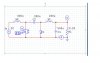
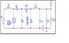
my project is to design cuk converter with output 20A and 5V..but when i try to simulate it using pesim, the output waveform is weird. could somebody help me..and another problem is that i found the non inverting cuk converter circuit..i would like to try it but i don't know how to calculate the parameters in the circuit..
 

Attachments

  • inverting cuk converter.JPG
    inverting cuk converter.JPG
    55.2 KB · Views: 2,010
  • non inverting cuk.JPG
    non inverting cuk.JPG
    58.1 KB · Views: 1,243
Last edited:
The term "weird' is too technical for me.:rolleyes:

Can you explain that in more detail or show the waveform?
 
can i know how the best way to calculate the parameter use in this cuk converter...
can i used electrolytic capacitor or ceramic because my capacitor always burned out. but it is difficult to find ceramic capacitor
 
I know the circuit on the left very well.
C2 will have current of near 40 amps. You will have trouble finding that capacitor.
You might first try using a 5 ohm load and get the simulator running first.
I normally use the same inductor value for each.
Real capacitors have resistance and a maximum current rating.
 
Status
Not open for further replies.

Latest threads

New Articles From Microcontroller Tips

Back
Top