Continue to Site

Welcome to our site!

Electro Tech is an online community (with over 170,000 members) who enjoy talking about and building electronic circuits, projects and gadgets. To participate you need to register. Registration is free. Click here to register now.

  • Welcome to our site! Electro Tech is an online community (with over 170,000 members) who enjoy talking about and building electronic circuits, projects and gadgets. To participate you need to register. Registration is free. Click here to register now.

Diagnosing a JVC DT-V100 CRT Monitor - more an electronics question...

Ed207

New Member
Evening!

I'm trying to diagnose a CRT monitor that appears to have no power. Don't worry, I'm used to working on live voltage systems and all precautions are being taken.

Strap in....this could be a long ride as I learn!

Symptoms - No power light or control on front panel. No HV as HV is turned on by a control circuit from the signal board, but the main power circuits still need to generate the voltages to run the signal and processing board, so I believe I'm correct in thinking I don't need the signal board connected to the main board to measure and test.

I've got the schematics (see attachment). My first question is more an electronics one.

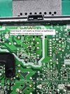
In Sheet 8 on the attachment, it shows the incoming mains and line filter board. The part I'm interested in to start with is connector CN1003 where it shows 140V (I think this is based on Japanese 100V as I'm getting 330V DC on a UK model monitor). Now this is DC as it's coming off the bridge rectifier, but then we go to the main PCB (Sheet 4 on schematics), where it comes into the board and goes to the first transformer (T1901).

Questions:
It's coming into the board as DC and appears to be arriving at the transformer T1901 as DC. I'd presume it would need to be AC for a transformer to work, otherwise it would get very hot and burn out. Am I missing something (quite obviously yes)?

The voltages coming out of the transformer are AC as expected, although one or two do not appear to be correct (7V, 2V and a wavering 4-9V). I think the 7V is prob correct, given it's going to a 6.3V or 5V rectifier.

Any advice on where to look next?
 

Attachments

  • dtv100cge - Schematics .pdf
    3.7 MB · Views: 59
The DC at the transformer is pulsed by the switching device IC1901. It might be running at a high frequency, possibly at many kHz. That produces the secondary voltages. PC1901 provides feedback to the switching device. R1916 may be (hard to tell by schematic) a thermal feedback, causing Q1902 and/or Q1902 to do some form of "control".
The output voltages are regulated by IC1931, 33, 35, and 36. Check the input (pin 1) and output voltages (pin 2) on those. If input voltages to those are "bad" (12V and 6.3V have higher input V), then the transformer switching may not be working properly. Input to the 12V and 6.3V regulator should be a few volts above 12V at least.
Measuring the secondary voltages as AC may not be accurate if your meter does not respond to the many kHz frequency of the AC signal. Measure the DC voltages at the capacitors instead - C1935, C1934 rated at 16V and 25V respectively. Measured voltage should be a fair bit less than the capacitor rating. Note that the grounds may be different on either side of the transformer. Measure secondary voltages against secondary ground (ground side of C1934, 35)
 
Last edited:
sagor1

At C1935 I get 2V (should be 8.6V measured on good monitor) and no output from pin 2 IC1936 as ON/OFF is low (this is controlled from signal board I believe, which is not getting power).
At C1934 I get 7.27V (should be 16V) and no output from pin 2 IC1933 or IC1934 . Again on/off pin 5 is low

At C1936 I get a wavering voltage between 2.8 and 7.4V (should be 117V according to a working monitor). This is the lower winding.

C1936 is giving me some funny readings and was a bit crusty on the underside. I'll probably swap this out to make sure, but that won't affect the other voltages.

Am I right in thinking that the issue may be on the live side, before the transformer?
 
Measure Pins on IC1901. Either that or any component it depends on is failing.
Slightly bulged lids on bulk e-caps (+) is the 1st visual check. Heat stress 2nd. Probe pin #'s on ICs and test nodes 3rd.
1741533766294.png


Mark clearly on above if you can.
 
If C1936 is faulty, that could be a problem. That provides voltage for feedback to the primary switching circuit via PC1901 near the bottom. With faulty feedback, none of the secondary voltages will be working properly. Without the 117V, PC1901 will not turn on and IC1901 will not switch the primary voltage thru the transformer. Check the diode D1934 that feeds C1936 as well.
There could also be a fault with IC1901 or PC1901 itself.
If possible, compare voltages (DC voltages) on the primary side around the semi-conductors if you have another working unit. Be careful, as these may be high voltages and dangerous. Check around Q1901 and Q1902, they both look at feedback on the primary side of the transformer. Again, use the primary ground for measurements, not the secondary ground, they are isolated from each other.
 
Check the voltage at the junction of D1910 and C1902, it should be over 12VDC (probably well over that). That circuit feeds unregulated +12VDC back to the power filter board via VCC12.
Vin for IC1901 is supplied via D1903. A short elsewhere on the VCC12 line on the power filter board could also pull down the Vin voltage.
I still suspect the IC1901 at this point, there is nothing else that would pull down the Vin voltage. Or, a remote chance Q1902 is faulty, that would be easy to remove and test.
Without lots of voltage and visual checks, I'm starting to guess now....
 
You've already confirmed C1936 is faulty (as it was crusty underneath, it will be high ESR), that is by FAR the most likely cause of your issue. It's the reservoir capacitor on the voltage rail that is monitored for the regulation, which is why voltages are fluctuating all over the place. It will absolutely, 100%, affect all voltage rails.

That specific capacitor is a VERY common failure on loads of different switch-mode supply circuits, and if you're unlucky (or leave it too long before you change it) it can cause catastrophic damage to the the rest of the unit, as PSU rails may be higher than is allowed, and often it kills large IC's, which are usually unobtainable.

So replace C1936, and keep your fingers crossed it's caused no further damage.
Apologies, I should have mentioned earlier, that cap was fine. The crusty was that it had been replaced before and they hadn't cleaned the board. I also tested the 330uF 450V cap and it's fine. The 2200uF caps are also good.

I'll work my way through the others a well. I'm sort of ignoring the small value caps, but possibly wrongly. I can remove a good working IC1901 from another monitor and test that, but currently assuming it's a passive.
 
Last edited:
Apologies, I should have mentioned earlier, that cap was fine. The crusty was that it had been replaced before and they hadn't cleaned the board. I also tested the 330uF 450V cap and it's fine. The 2200uF caps are also good.

I'll work my way through the others a well. I'm sort of ignoring the small value caps, but possibly wrongly. I can remove a good working IC1901 from another monitor and test that, but currently assuming it's a passive.
Have you checked them with an ESR meter?, if not you haven't checked them at all?.

Do you have an oscilloscope?.
 
Have you checked them with an ESR meter?, if not you haven't checked them at all?.

Do you have an oscilloscope?.
I have, yes. All within tolerance and reactance. My meter is not the best (always been reasonably reliable though), but got a new one arriving Monday

Dug out my oscilloscope today. What should I be checking?
 
I have, yes. All within tolerance and reactance. My meter is not the best (always been reasonably reliable though), but got a new one arriving Monday

You don't mention ESR, and that's what's critical, value and reactance are pretty well irrelevant, did you use an ESR meter - a capacitance meter is no use. Normal testing very often shows them as good, it's the ESR which has failed - not shown by a capacitance meter.

Dug out my oscilloscope today. What should I be checking?

Check the ripple on the secondary rails, if the capacitors (like C1936) are high ESR the rail with have excessive (and obvious) high frequency ripple on it.

Basically you can check the capacitors in-circuit (almost always), with it powered down, using an ESR meter - this often requires you to remove the PCB to get to the bottom, to get on to the capacitors.

An alternative method, leaving the PCB in situ, is checking the ripple on the secondary reservoir capacitors using an oscilloscope - this obviously requires the unit to be powering up to 'some degree', if it's dead you're back to an ESR meter, and removing the board. It's also quick and easy, because you can check on the outputs of the rectifier diodes, which are easily located, and easy to connect the scope to. I'd often use this method on satellite receivers, as the bottom of the PCB isn't accessible without removing it.

Some units use a 'pi' type filter on one or more of the outputs, two capacitors joined together with an inductor - if the first (reservoir) capacitor goes high ESR the second one still filters the rail, but at a much reduced voltage, due to losses through the inductor - the scope test on the rectifiers still spots this though.

In my previous career I repaired thousands of switch mode PSU's in TV's, satellite receivers, etc. - and replaced many thousands of electrolytic capacitors.

I appreciate this is probably a 'one off' for you, but as I was almost certainly going to see multiple examples of the same units, I always documented what had failed - particularly in the case of catastrophic PSU failure - and I made up drawers containing the parts that I had found failed (as a kind of repair kit). If I ever came across another component failure, I added it to the list and the draw :D

I was doing it professionally, and once I'd gained experience on a specific unit, the first thing I'd do is replace all the components that I'd previously had fail, this saved masses of time - and reduced labour costs to under an hour for almost all such repairs, easily swamping the added costs of a few components. You might have spent three days on the first one you saw, and you can't charge three days labour :D - but hopefully the losses involved on the first one are recovered from the higher profits on later ones (spending 15-20 mins while charging for an hour).

Incidentally, on a couple of TV chassis's (a Grundig and a Tatung), they used almost identical PSU's, same IC, same transistor, almost identical circuit - yet if the main reservoir went O/C (the big 350V one on the incoming mains) the Grundig PSU self destructed (requiring my kit of bits, plus the large electrolytic). Yet the almost identical Tatung set carried on working, you got a bit of hum and a small picture, but the set still worked, and you just needed to change the electrolytic - job done. I could never get my head round that?.
 
You don't mention ESR, and that's what's critical, value and reactance are pretty well irrelevant, did you use an ESR meter - a capacitance meter is no use. Normal testing very often shows them as good, it's the ESR which has failed - not shown by a capacitance meter.


Check the ripple on the secondary rails, if the capacitors (like C1936) are high ESR the rail with have excessive (and obvious) high frequency ripple on it.

Basically you can check the capacitors in-circuit (almost always), with it powered down, using an ESR meter - this often requires you to remove the PCB to get to the bottom, to get on to the capacitors.

An alternative method, leaving the PCB in situ, is checking the ripple on the secondary reservoir capacitors using an oscilloscope - this obviously requires the unit to be powering up to 'some degree', if it's dead you're back to an ESR meter, and removing the board. It's also quick and easy, because you can check on the outputs of the rectifier diodes, which are easily located, and easy to connect the scope to. I'd often use this method on satellite receivers, as the bottom of the PCB isn't accessible without removing it.

Some units use a 'pi' type filter on one or more of the outputs, two capacitors joined together with an inductor - if the first (reservoir) capacitor goes high ESR the second one still filters the rail, but at a much reduced voltage, due to losses through the inductor - the scope test on the rectifiers still spots this though.

In my previous career I repaired thousands of switch mode PSU's in TV's, satellite receivers, etc. - and replaced many thousands of electrolytic capacitors.

I appreciate this is probably a 'one off' for you, but as I was almost certainly going to see multiple examples of the same units, I always documented what had failed - particularly in the case of catastrophic PSU failure - and I made up drawers containing the parts that I had found failed (as a kind of repair kit). If I ever came across another component failure, I added it to the list and the draw :D

I was doing it professionally, and once I'd gained experience on a specific unit, the first thing I'd do is replace all the components that I'd previously had fail, this saved masses of time - and reduced labour costs to under an hour for almost all such repairs, easily swamping the added costs of a few components. You might have spent three days on the first one you saw, and you can't charge three days labour :D - but hopefully the losses involved on the first one are recovered from the higher profits on later ones (spending 15-20 mins while charging for an hour).

Incidentally, on a couple of TV chassis's (a Grundig and a Tatung), they used almost identical PSU's, same IC, same transistor, almost identical circuit - yet if the main reservoir went O/C (the big 350V one on the incoming mains) the Grundig PSU self destructed (requiring my kit of bits, plus the large electrolytic). Yet the almost identical Tatung set carried on working, you got a bit of hum and a small picture, but the set still worked, and you just needed to change the electrolytic - job done. I could never get my head round that?.
Thanks Nigel. Excellent advice. I'll wait for the new meter to arrive tomorrow and get going on the caps then. I can at least check some readings with the scope today.

Funnily enough, I've got 4 of these monitors, and two are bad, so I'm hoping it's the same thing for both. I've been reading up on SMPS and possible faults for varying voltages, so I'll try and work through the usual issues for this as well. So far the opto isolator looks okay, although the incoming and outgoing voltages are fluctuating.

The underneath of the board on the left side of the transformer looks "browner" than the working version, and has a slightly sticky residue which may just be heated solder mask. Top side looks fine though. I'm currently concentrating on this area.

EDIT: I forgot to mention that the PSU is ticking when plugged in.
 

Attachments

  • good board rear.jpg
    good board rear.jpg
    3.8 MB · Views: 32
  • badboard top.jpg
    badboard top.jpg
    2.5 MB · Views: 35
  • badboard rear.jpg
    badboard rear.jpg
    4.2 MB · Views: 32
Last edited:
For 'ticking' check the secondary rectifiers aren't S/C, it apparently uses ones in parallel, and these make them very prone to failing S/C. You can check them from the top, with a simple diode test (although you can't tell which of the parallel diodes is S/C - but you should change both, for ones out of the same packet).
 
For 'ticking' check the secondary rectifiers aren't S/C, it apparently uses ones in parallel, and these make them very prone to failing S/C. You can check them from the top, with a simple diode test (although you can't tell which of the parallel diodes is S/C - but you should change both, for ones out of the same packet).
Getting one diode as short circuit for a few seconds, then it stops. Reversing the leads gives the same result. I'll take it out of circuit and test properly. I'm guessing this is a cap charging though?

Frustratingly both test okay out of circuit. Back to the drawing board.
 
Last edited:
So quick update. Tested all the secondary rectifiers, and discovered the clicking stopped when I disconnected D1934 from the circuit, so the fault must lie on that line. Opto isolator checked out fine, and was starting to work on testing each stage when my thermal camera arrived. I don't mind a bit of cheating if you don't! :)

R1963 was glowing nice and hot when turned on. Checked it and it's fine. but that led me to Q1955 MOSFET, which is shorted across S/D. New ones on the way. Will update tomorrow once they arrive.
 

New Articles From Microcontroller Tips

Back
Top