Continue to Site

Welcome to our site!

Electro Tech is an online community (with over 170,000 members) who enjoy talking about and building electronic circuits, projects and gadgets. To participate you need to register. Registration is free. Click here to register now.

  • Welcome to our site! Electro Tech is an online community (with over 170,000 members) who enjoy talking about and building electronic circuits, projects and gadgets. To participate you need to register. Registration is free. Click here to register now.

Discussion: Rules For Drawing Readable Schematics

Status
Not open for further replies.
Many of the ideas that have been posted in this thread are merely additions to the guidelines, and are not really pointing out flaws. What would be ideal is if there was some standard that included a complete list (however difficult that would be) of all rules that any designer should follow to keep schematic drawing styles consistent worldwide.

One of the standards that is not kept to and widely misused is the symbol for earth ground, where it is customarily used for power common, this is aggravated by publications such as Art Of Electronics, who either misuse the symbol throughout the book, or intend all the examples to be ground referenced.
Dr Archambault has mentioned this in one of his video lectures.
Where circuitry actually has a ground reference but requires a secondary circuit to be isolated from it can be misleading and catastrophic to say the least when the same symbol is used for both, which happens frequently.:confused:
Max.
 
And I have never agreed with the saying you mention. Sure, sometimes it's true, but it's a horrid stereotype that is more often wrong than right (in my experience).

I think you interpret "do" way too narrowly.

John
 
A lot of members can't afford the luxury of schematic software... As far as I'm concerned, a schematic should just be " legible ".....

There are several free schematic software packages out there, I graduated from an older expensive Orcad package to Kicad which compares favourably to the legacy version I was using
Max.
 
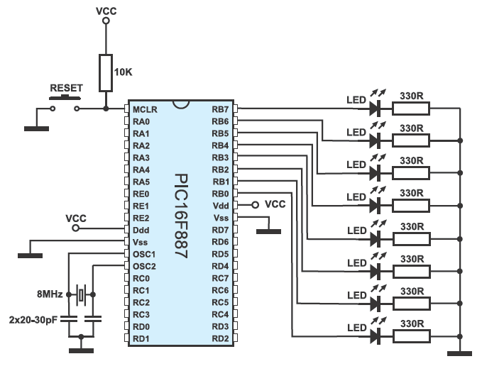
If you loook at the 8051 tutorials... This was done in MS paint!! I have several schematic software drawing packages, but as far as I can see, visual is better..

I got the idea from mikroC templates.. The more visual the drawing, then the better understanding..

look at this schematic..
fig4-33.gif

Really visual....
 
I agree with Ian. Must look nice and clear. That's all.

Who cares if you followed the rules or broke them. Rules are for people who don't want to think for themselves.

I once read a book about how to write technical manuals. It said: "As a rule of thumb, do not use stupid expressions, such as 'as a rule of thumb ...' ".
 
.... Must look nice and clear. .....

"Nice and clear" isn't quite enough. It must be easy to understand, particularly if you're asking for help.

If a schematic isn't easy to follow, the people who may be in the best position to help may pass on by if it's too difficult to follow. The guidelines help make a schematic easier to understand.

Also, I don't think it's been brought up yet. Post a picture or PDF of the schematic - not a file from the schematic capture program. Not everyone will have the same software.
 
Last edited:
If you loook at the 8051 tutorials... This was done in MS paint!!
I also make schematics in MS Paint. I copy and paste parts and parts of datasheets.

Your schematic is very clear but I think instead of "VCC" it should have the number of volts (3.3V or 5V?).
 
Your schematic is very clear but I think instead of "VCC" it should have the number of volts (3.3V or 5V?).
AG!! Not mine... MikroE did that one.... But I see what you mean.. None of mine specify Vcc levels... ( I assume they would look at the datasheet.. Ha Ha Ha Ha!!!!)..
 
Although its ancient I used Visio v3 to do schematics way back, I now have to fight with Eagle... , and in my 50 years experience the " Teacher " thing is correct....
 
Also, I don't think it's been brought up yet. Post a picture or PDF of the schematic - not a file from the schematic capture program. Not everyone will have the same software.
Just seen this!!

I used to use WMF for all my drawings....(Windows MetaFile) I stopped as Windows ended up the only ones not supporting it!!! The only way to view WMF on a PC with XP or later is via explorer...
 
I agree that PDFs are really the best way to go. They can be viewed on virtually any platform, file sizes are (generally) very small, it's easy to read and zoom in, generally provides a very good quality image, and is very easily portable.
 
I agree that PDFs are really the best way to go. They can be viewed on virtually any platform, file sizes are (generally) very small, it's easy to read and zoom in, generally provides a very good quality image, and is very easily portable.
The only thing with PDF's is you HAVE to download them ( My firefox in app PDF reader doesn't work ) That means shed loads in my download folder!!
 
The only thing with PDF's is you HAVE to download them ( My firefox in app PDF reader doesn't work ) That means shed loads in my download folder!!

If you're getting them online, then sure. But it is still easy to view them, all you need is a PDF reader, of which there are hundreds out there.
 
What version of Firefox? I have used it for quite a few years now and it opens PDF's without saving. Foxit reader is what it's called on my versions. You have to actually tell it to save what you want to keep.
 
Yes, when I used Firfox it was great, just view the PDF, I had to switch to Chrome because of the Utube issue and I find it tiresome, that I have to save a PDF before viewing.
Max.
 
Most PDF viewers need a local copy...

Few years ago, I've got a virus through Adobe Acrobat Reader which automatically opens PDFs. Had to rebuild the computer. Took me few days. I don't use Adobe any more. I now save PDFs and watch them with off-line reader. I have quite a collection :)
 
Status
Not open for further replies.

New Articles From Microcontroller Tips

Back
Top