throbscottle
Well-Known Member
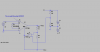
I found this circuit to provide a differential output to an in-amp in a datasheet for one of Analogue's in-amps. I'm actually using Microchip's MCP6N11 in-amp, which uses 2 gain setting resistors. I think the choice of opamp in the circuit isn't very important.
Microchip don't publish a simulation for their inamp, so I just used any old one I found in LTSpice.
The gain setting resistors for the MCP6N11 are connected from output to Vfg, and Vfg to Ref, so in this circuit they will also appear to be in parallel with R3 and R2.
The gain setting resistors will be 4k32 and 7k68 (if I can get these values) to give a gain of 1.5625 (so 1.6v in will give 2.5v out), the Vfg and Ref inputs of the MCP6N11 are high impedance, so the load on the in-amp will be 12K in parallel with R2 and R3. The in-amp itself has an output impedance of 900R.
So my question is, R2 and R3 should be equal, but what value should they be? Highest I can get away with? Or is there some optimisation I can do here?