Continue to Site

Welcome to our site!

Electro Tech is an online community (with over 170,000 members) who enjoy talking about and building electronic circuits, projects and gadgets. To participate you need to register. Registration is free. Click here to register now.

  • Welcome to our site! Electro Tech is an online community (with over 170,000 members) who enjoy talking about and building electronic circuits, projects and gadgets. To participate you need to register. Registration is free. Click here to register now.

Schottky diodes question for circuit

robdean

New Member
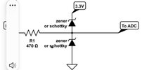
I am trying to order schottky diodes for the attached circuit. I am trying to protect a 3.3v esp32 input pin from a voltage over 3.3v. The pin will be provided 0-4ish volts. And convert that voltage into a reading. My question is. I can not find a 3.3v schottky diode. Or anything lower then 10v. I thought they were like zener diodes and i would need one with a 3.3v rating. Am i wrong are they rated different? Where do you all buy your low voltage schottky diodes?

Also i cant use a voltage divider since most of my reading will be very low volage and undetectable if i divide the voltage.

Thanks any input would be appreciated.
 

Attachments

  • Screenshot_20240420_225038.jpg
    Screenshot_20240420_225038.jpg
    81.2 KB · Views: 38
There are two separate ways of protecting the input against over-voltage where the voltage will be above the 3.3V of the supply.

The first is to use a diode in the top position. The voltage will be limited to a level that is more than the supply voltage by the diode’s forward voltage. With a 3.3 V supply and a Schottky diode, the voltage will be limited to around 3.6 - 3.7 V.

The second is to use a zener diode in the bottom position. The voltage will be limited to the zener voltage, for instance about 3.3 V with a 3.3 V zener.

A Schottky diode should never be used at a voltage where it will start to conduct in reverse. The big advantage of Schottky diodes is their smaller forward voltage drop.

Zener diodes are designed to work when conducting in reverse. The reverse breakdown voltage of a zener diode is the zener voltage. Zener diodes can be used when forward biased and they will conduct at about 0.6 V like most silicon diodes. A 3.3 V zener in the bottom position will protect the input from exceeding 3.3 V or from going lower than -0.6 V.
 
Last edited:
My question is. I can not find a 3.3v schottky diode. Or anything lower then 10v. I thought they were like zener diodes and i would need one with a 3.3v rating.
No they are not like Zener diodes, they are like regular diodes.
They just have a lower forward voltage drop.
The voltage rating is the maximum reverse voltage they can operate at.
 
Also, if the voltage exceeds the rated voltage of a a zener diode, the diode will begin shunting current, and if exposed to a higher voltage for too long, it can get hot or burn if not current limited.
 
I have been working with my circuit a bit. See attached. The resistance in the pic is the actual resister readings. My issue is the line with 3.17volts in real life is showing 1.688volts. I know the program i have in the picture is perfect world but that is way lower then i thought it should be. If i take out the zenier diode i get 3.4998 volts. So its keeping it from going over 3.3v but why is it keeping it so low and not around that 3.17volts? Sorry i am not an expert just a hobbyists working on a fun project.

The resister that is 9.78k will be a water temp thermister(i think its called) that will have a range from 115 Ohms to 55000 Ohms. I dont need the higher Ohms which will be very cold temps. My real world range i want to use is around 110 Ohms to 9000 Ohms (hints my 9.7k resister to test my protection circuit) . That being said if we get a really cold unusually cold winter it could drop the temp so the thermister gives me a voltage over 3.3v taking out the esp32 chip.

Thanks you all have been very helpful. I am learning a lot!!
 

Attachments

  • Screenshot_20240423-212850_EveryCircuit.jpg
    Screenshot_20240423-212850_EveryCircuit.jpg
    438 KB · Views: 44
It's very difficult to read an upside down circuit :D

But why are you feeding the potential divider from 5V?, why not just feed it from the existing 3.3V supply for the ESP32, and cure all your potential problems?.
 
It's very difficult to read an upside down circuit :D

But why are you feeding the potential divider from 5V?, why not just feed it from the existing 3.3V supply for the ESP32, and cure all your potential problems?.
This may be the dumest thing i have said in a long time but the sensor is a 5 volt sensor. But now that i think about it, it uses resistance so it should not matter. Right?
 
This may be the dumest thing i have said in a long time but the sensor is a 5 volt sensor. But now that i think about it, it uses resistance so it should not matter. Right?

There is no 'sensor', just a thermistor (according to your diagram) - which is of course a kind of sensor, but has nothing to do with voltage.
 
So i am still wondering why my circuit did not work. Any thoughts?
The voltage would not go above 1.688volts. I wanted it to top out and bleed off closer to 3.3v. The diode when added basicly halfed the voltage. My understanding was it should have bled off more and more voltage as it got to 3.3v. I expected it to be around 3.17volts(see secound pic) give or take. But it halfed my voltage the entire way from 0 to 5volts. Sorry i am sure i am not fully understanding how it should work. i just want to understand and learn. Thanks
 

New Articles From Microcontroller Tips

Back
Top