A few "home improvements" to my kitchen radio... Tim Allen style.
I'm replacing the onboard linear transformer with an external SMPS, replacing the amplifier board with a "T" amp chip amp upgrade, and replacing the OEM speakers with 10x better drivers from Partsexpress. Everything has arrived in the mail. The CD Radio is disassembled on the workbench. The SMPS is awaiting judgement.

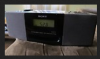
Here's the Sony CD/AM/FM. Two main 3.5 inch speakers and a rear 4.0 inch "sub" woofer.

A couple pages of the basic specs from the internet
**broken link removed**
**broken link removed**
The new Amp

And the page I purchased it from....
**broken link removed**
It's 10x the sound quality of the existing amp in the Sony.
The Vifa 3.5"s and Dayton Neodymium 4" woofer came in a little box a few days ago from Partsexpress.
I'm controlling the amp above right off of the preamp board in the Sony

...tapping into the main volume pins on the bottom side.

As to the current requirements. The amplifier vendor provides nothing specific on this, but suggests a 15 to 20vdc SMPS to drive the amp. SMPS sold online for this size chip amp are commonly 2.0 amps.
I know how to measure current draw for a known input (120vac) using a DMM, but unfortunately the radio is completely disassembled right now so I cannot get in between the linear transformer onboard while it's running to check for current. It don't think it's exceeding 3 amps though.
The onboard linear xformer.


I could just leave it in there. But then I'd have to keep the 120 cord connected and try to mount the SMPS in the radio. No room for that.
I'd prefer to connect to the radio with the single 19.5vdc cord. The OEM xformer has 9 and 15vdc clearly marked outputs. I can connect directly to the new amp with 19.5vdc and then feed the 9 and 15 volt and ground wires leading out of the old xformer.
Would the circuit required for stepping down and splitting these voltages be complicated with various IC regulators and such?
I'm replacing the onboard linear transformer with an external SMPS, replacing the amplifier board with a "T" amp chip amp upgrade, and replacing the OEM speakers with 10x better drivers from Partsexpress. Everything has arrived in the mail. The CD Radio is disassembled on the workbench. The SMPS is awaiting judgement.
Here's the Sony CD/AM/FM. Two main 3.5 inch speakers and a rear 4.0 inch "sub" woofer.
A couple pages of the basic specs from the internet
**broken link removed**
**broken link removed**
The new Amp
And the page I purchased it from....
**broken link removed**
It's 10x the sound quality of the existing amp in the Sony.
The Vifa 3.5"s and Dayton Neodymium 4" woofer came in a little box a few days ago from Partsexpress.
I'm controlling the amp above right off of the preamp board in the Sony
...tapping into the main volume pins on the bottom side.
As to the current requirements. The amplifier vendor provides nothing specific on this, but suggests a 15 to 20vdc SMPS to drive the amp. SMPS sold online for this size chip amp are commonly 2.0 amps.
I know how to measure current draw for a known input (120vac) using a DMM, but unfortunately the radio is completely disassembled right now so I cannot get in between the linear transformer onboard while it's running to check for current. It don't think it's exceeding 3 amps though.
The onboard linear xformer.
I could just leave it in there. But then I'd have to keep the 120 cord connected and try to mount the SMPS in the radio. No room for that.
I'd prefer to connect to the radio with the single 19.5vdc cord. The OEM xformer has 9 and 15vdc clearly marked outputs. I can connect directly to the new amp with 19.5vdc and then feed the 9 and 15 volt and ground wires leading out of the old xformer.
Would the circuit required for stepping down and splitting these voltages be complicated with various IC regulators and such?
Attachments
Last edited:
