Continue to Site

Welcome to our site!

Electro Tech is an online community (with over 170,000 members) who enjoy talking about and building electronic circuits, projects and gadgets. To participate you need to register. Registration is free. Click here to register now.

  • Welcome to our site! Electro Tech is an online community (with over 170,000 members) who enjoy talking about and building electronic circuits, projects and gadgets. To participate you need to register. Registration is free. Click here to register now.

ECG device with AD620

Status
Not open for further replies.

etwing

New Member
Hi all,
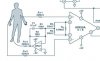
I have built a ECG device with AD620. The circuit was shown in ECG circuit.JPG attached.
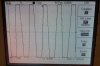
However, the output of AD620 was not as expected. I took a picture of it and it was attached as well.
Can somebody help explaining why the output is like this?
Thanks a lot.
 

Attachments

  • ECGcircuit.JPG
    ECGcircuit.JPG
    21.2 KB · Views: 10,620
  • FxCam_1306062024354.jpg
    FxCam_1306062024354.jpg
    261.5 KB · Views: 1,284
That is approximately 50 Hz (maybe 60 Hz) pickup of background noise from the mains. Increase your attenuation and you will see the full wave.

John
 
You are just seeing the background noise, which you are picking up from the leads, grounds, and maybe your power supply. If you are connected to a person, that person is just an antenna for all of that background.

Heart rate is approximately 1Hz by comparison. Your scan width is way too narrow at this point. Later you can trigger on the EKG QRS complex, but first you have to find the pulse. Try something that will capture a 1 Hz signal. It appears you are set on 10 mS per division. Go to 500 mS per division. You also need to get the peaks on scale for your oscilloscope.

John
 
Thank you again.

I have changed the Rg from 6.98K to 30K to reduce the gain, but I could still only see the noise. Will there be any problem with the two 22K resistors? Should I adjust the value as well?
 
I think I have misunderstood attenuation.

Higher the gain gives greater CMRR and also the attenuation (please tell me if I am wrong), so I should increase the gain for better noise reduction.
But it showed no improvement at all when I changed the gain from 8 to 990, still only noise was observed.

Please advise how to remove the unwanted noise. Thank you so much.
 
I think you should use shielded (screened) input cables so that they don't pickup mains hum.
You also need proper skin contacts that have conductive grease.
 
Thank you audioguru.

Would it be helpful if I shorten the length of the input cables or use twisted cables? because I don't have shielded cables right now
 
If using the shielded cable, should the shield be connected with output of Right leg driver or the system ground?
 
If using the shielded cable, should the shield be connected with output of Right leg driver or the system ground?
I wondered about that also. I think the right leg signal cancels mains hum picked up by the patient. then the shields connect to 0V in the circuit.
 
I used shielded cables and connected the shield to system ground. However, still only noise was observed.
Which part in my circuit went wrong?:confused:
 
I found out that there was a 5V DC offset in the AD620 output. Can somebody suggest how to remove the DC offset?
 
I found out that there was a 5V DC offset in the AD620 output. Can somebody suggest how to remove the DC offset?
An AD620 with low gain has a very low offset voltage. The right leg driver cancels most common-mode hum pickup and any DC offset.
I think you probably have an input that is not connected to the patient.

When I had an ECG, the nurse shaved spots on my chest and "scratched" the skin. Conductive grease was used under the probes.
 
I see... Thank you audioguru. I will check on that later.

BTW, is there any method to check the functionality of Ag/Cl sensor (which is what I used)? I hope they were not damaged when I soldered them together with wires...
 
Status
Not open for further replies.

Latest threads

Back
Top