Continue to Site

Welcome to our site!

Electro Tech is an online community (with over 170,000 members) who enjoy talking about and building electronic circuits, projects and gadgets. To participate you need to register. Registration is free. Click here to register now.

  • Welcome to our site! Electro Tech is an online community (with over 170,000 members) who enjoy talking about and building electronic circuits, projects and gadgets. To participate you need to register. Registration is free. Click here to register now.

Egg Incubator repair help

tonywolfin

New Member
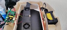
Hello, first time post here and not much electronics knowledge, but a willing spirit! I am trying to repair my failed RCOM PX20 Digital egg incubator. It's quite an old model however I do like how it works.

I was using it until couple of day ago, it was on and working properly, then i unplugged it to move it and when I plugged it back, it did a small noise and won't start anymore.

I did the following tests with a multimeter :

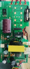
1- I tested the input when plugged at the CN1 and CN2 connections and it has 236V (France)
2- I did a continuity beep test on the transparent fuse, it beeps.
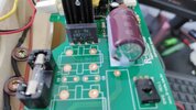
3- I tested what I think is the transformer in yellow. It seems to have 2 legs on one side and 4 on the other. The 2 on one side seems to beep when unplugged.
4- I tested the bridge rectifier KBP206S, it has a + AC - writing on it. Unplguged, I tried every combination with the conitnuiy test, but no beeps at all in any direction. I plugged it and tried to get the + and - tested together with my multimeter DC mode 20v and 200V but both come up with -1 on the screen.

That's how far i am (with ChatGPT), are you able to support and help me test and see what could be wrong so I can replace it ? No electronics store nearby and shipping is expensive, so I would rather order everything in one go rather than multiple times if possible. Thanks for your help and hope I can fix this :)

Tony
 

Attachments

  • circuit 2.jpg
    circuit 2.jpg
    2.9 MB · Views: 20
  • WhatsApp Image 2025-03-31 at 19.24.12.jpeg
    WhatsApp Image 2025-03-31 at 19.24.12.jpeg
    176.4 KB · Views: 18
Can you get a photo of the back of the board?

If your only bit of test equipment is a multimeter that can only read up to 200 V on DC, fault finding this is going to be very difficult.

I would expect about 350 V DC between + and - on the rectifier when it is working, which probably shows up as "-1" to indicate an overload on a cheap multimeter.

Can you measure the voltages between the pins at the bottom of the photo?

That is a power supply and the device labelled TH1 is a triac that turns on and off the heater. I am not sure what controls the triac. Can you show what else there is in the incubator, that the connections at the bottom of the photo go to?
 
Thanks for the quick reply. I uploaded a picture of the multimeter I'm using, Your guess is right, its likely a cheap model I had for years. I am considering buying a new, any tips would be welcome. I also posted a picture of the bottom of the board. The components of the machine are the following : 2 fans (red and black wires) one turning motor (yellow and black wires) then the rainbow/grew cable goes to the digital display in the front. It also connects to a small PCB board that I think has a humidity detector and thermometer next to the digital display. I think there is also a heating element upfront that goes into the water, you can see some chalk traces on it. it also has a fan next to it.

I measure with Setting 20V DC the 3 legs of the TH1 component, I get a fluctuating reading of 0.00 to 0.06 max with the - appearing every now and then. Hope this helps
 

Attachments

  • WhatsApp Image 2025-04-01 at 09.13.05.jpeg
    WhatsApp Image 2025-04-01 at 09.13.05.jpeg
    188.6 KB · Views: 14
  • 1000046210.jpg
    1000046210.jpg
    320.2 KB · Views: 12
  • 1000046209.jpg
    1000046209.jpg
    347.7 KB · Views: 11
One more thing, the rectifier has 109 on leg 1 and 2 and also 109v on legs 3 and 4. while it has 339V on 1 and 4 and nothing on 2 and 3. Not sure how to interpret that. Thanks
Perfectly correct - you're measuring from the negative leg of the bridge, so the negative leg will read zero - when you measure the positive leg, then it reads full rectified mains (350V odd), the other two legs are the AC input and will read roughly half of the positive pin. Anything wrong in that part of the circuit, and the voltages on the bridge would be catastrophically wrong, there's also no point measure on the AC inputs, or on the negative pin, you only need to measure from negative to positive.

The fault is unlikely to be there anyway, it's FAR more likely to be in the switch-mode circuitry - but that's not really a place for beginners to be messing.
 
thanks for the reply. I am not ready to give up on it to be honest. I think it's quite an expensive piece of equipment and I would like to try and fix it with your support. Would you be willing to support in helping me go further? thanks
 
Can you measure all the voltages on the pins on the white connectors and on the multicoloured cables? It might not be the power supply, but those measurements would show it one way or the other.
 

Latest threads

New Articles From Microcontroller Tips

Back
Top